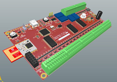
As I continue to work on the train layout, one thing I am realizing is that I dont have enough turnout and signal control boards from the previous build 10 years ago. That design had a few issues and was more complicated than it needed to be. So I did an update, corrected a few errors, made changes for parts that are not available right now and simplified the design.
One big change was driving the relays in the turnouts and signals. I need to drive relays in the
turnouts/signals for 100ms to 400ms, depending on the type, and only
one at a time is ever activated.
The first issue is providing enough drive to fully turn on the FET,
thus lowering Rds and reducing heat. With 3.3VDC that can be
problematic depending on the FET. I need flexibility in buying so I
am wanting to use 5VDC. The MSP23S8 I/O Expander has to run at 3.3V, because the
interface to the PIC runs only at 3.3V. But the I/O expander has open
drain outputs good to 5.5VDC, so it seems attaching a pull-up
resistor to 5VDC will improve my drive problem, since a Vgs of 5V will
fully turn on most of these FETs.
The next issue is at startup when nothing is defined. The MSP23S18
I/O pins are inputs on reset, which will float the GATE of the
driving FET. If the BIAS point (see schematic) is connected to 5VDC, then until the
MSP23S18 is programmed and all of the outputs are set to zero, all
of the FETs will be on. This will not be good for the relays as
the relays in a turnout will be fighting each other. So I came up
with an idea of a BIAS control. A single FET connected to a PIC I/O
pin. This will hopefully do the following:
On POR: RB0 will be an input, Rin will turn the FET on enough to
drive the BIAS point to GND. This should turn off all the relay
FETs and everything will be stable.
Initialization: Once RB0 is set as an output it will be set high,
to keep the BIAS point at GND while the MSP23S18 is initialized for
the outputs to be all ZERO.
Finally: Once the MSP23S18 is initialized, then RB0 can set to
ZERO, which will change the BIAS point to 5VDC.
Below is a reduced schematic of how this will be done.


No comments:
Post a Comment