
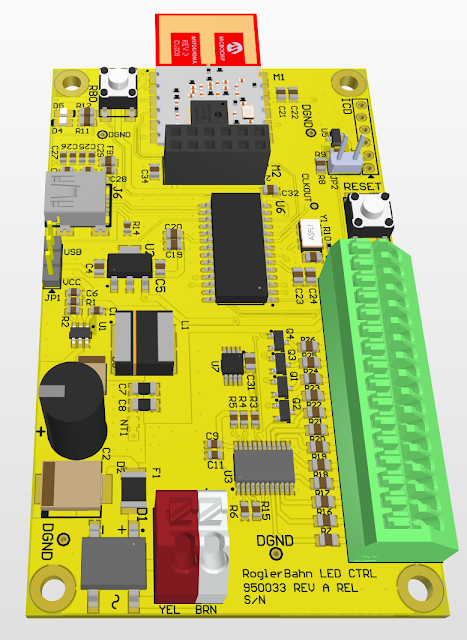
I completed my last design for a while. This is the LED controller for the lights in the buildings, freight yards, etc. It has 12 LED channels, 8 of them are controlled by an I2C based LED controller and 4 by the PIC. The 4 PIC channels are connected to PWM channels and the LED controller has individual PWM controllers for each of the 8 channels. This will allow for some different lighting effects besides just off and on.
This uses the PIC18F27J53 processor and a MRF24J40MA MiWi transceiver. As I have done with the switch/signal board, I also included a connector for the PMOD version of this. I have several of those and will have to use them until the MiWi Module becomes available from other than the resellers.
This was done on Sunday, but during the final purchase review I
discovered that the LED controller I picked did not do everything I
wanted. I had discovered a LED controller (LP5569) from TI when
working on the new Brick Controller design. It was a 9 channel
(triple RGB) sink style controller, but with a current limit of 25mA
that was software controlled. That was OK for a Lego display and
might have worked for the train. But that IC disappeared, with next
availability sometime in 2023. I found a firmware compatible
earlier version (LP55231) at a Chinese reseller so I bought the MOQ
qty of 20, but at 5x the price. This new LED controller is a source
style, 25mA limit. After much thought on how this PCB would be used
in layout lighting, I decided that 25mA was too much of a
restriction and in the end did not like the source style. I had
considered placing a N channel FET in each channel to increase the
current limit, but that just seemed like adding a lot of complexity.
So after a day of searching for alternatives that can be purchased,
I found one from NXP. This is an 8 channel sink style controller,
each channel can sink 100mA. The TI controller was in nice compact
24 pin QFN with a big power pad on the bottom. The NXP is in a 24
TSSOP package, though it has 4 ground pins. We will see how it
handles lots of current. This NXP does come in a QFN, but it is
being discontinued. I had to give up the RGB feature of the
LP5569/LP55231, but I have not found an application for that feature
yet.
This design has a DC-DC converter that converts the 16VAC to 5VDC @
1A+. The processor and the radio use about 50mA, so the rest is
dedicated to lighting power. It also has 8K or bigger I2C EEPROM
for storing the lighting configuration, so on power up a standard
lighting arrangement will be executed. I wanted to use a SPI
EEPROM, since the other two boards use those. But the PIC18F27J53
has 2 MSSP devices, but has only one I2C port and it is fixed
(electrical requirements of I2C dont allow for reassignment) and
uses the same pins as the fixed SPI port. So when you use an I2C
port on this part, you loose a SPI port. Since the radio module
wants to be on its own SPI port and the LED controller needs an I2C
port, the EEPROM became I2C. Which created its own availability
nightmare. Mostly finding an IC package and industry standard
firmware access I might be able to buy in the future.
No comments:
Post a Comment