Tuesday, February 28, 2023

Brick Light Connection


Here is a new connection scheme.  The two pin connector is the white rectangle in the picture.  I was continually frustrated by all the wires running between modules and around the outside.  This way all wiring can be inside the module and this small keyed 2mm connector will provide the USB power for the electronics.  Not sure how this going to work with USB Data connections yet, but for simple ON/OFF lighting and Light Buddy 2, this is perfect.  This next picture shows the USB connection, where I have but the mating 2mm connector on a USB cable.  In the end I have ordered these USB Connectors from Amazon and will build my own out of 26 AWG wire I have.

Here is what they are made of.  These two are actually the same PCB board.  The design intent was to be able to lock this into place so it would not move when connecting to it.  Sine the PCB is 1.6mm thick, I am 1.6mm short of having an exact connection in the Brick World.  So I designed the PCB so that you can have two configs, depending on how much support is needed.


With three connectors on the inside, there is only room for a 1 X 1 tile on the bottom for a connection.  If only one connector is needed inside, then a 1 X 2 tile can be used to give extra support.  These two configurations are shown here.  It is hard to see the tiles, since they are black.  I wanted them to blend into the module base.

By absolute dumb luck, that was not necessary.  The connector is 4.8mm tall, which gives a total height of 9.6mm, the height of a standard brick.  This picture shows how a standard set of bricks will lock the PCB in place.  The only use for the 1 X 2 tile configuration that I can see now is that small set of cases where there is no brick across the top locking in it place.  The two 1 X 2 tiles should provide enough connection force to keep the PCB in place.

One last item is wiring in place.  This picture shows the wiring coming through the base and the two connections plug into the mounted PCB.  Then I used two 1 X 3 plates with two 1 X 1 round plates.  By mounting in the the round plates in the tubes, a small amount of horizontal space is left for the wires to pass through.  This acts a wire harness attachment point and is useful for keep the wiring bundle neatly contained and out of the way.

There are other ways to this.  Here is another example.  This uses 1 X 1 round plates to capture the wire against the 2 X 8 brick.

I like this method since it completely captures the wire harness.  Unfortunately the connector will not fit through the hole.  So the connector has to be installed after the wiring is run.  This could be difficult, depending on the length of wire from the last part it passed through.

I will have more thoughts on this as time goes on.  I have only recieved these PCBs and I am still playing with configurations and what might be more optimal implementations.


Monday, February 27, 2023

Working on the Cliff Wall


As the Space Base transforms to more detail and more solid structure, I am starting on the left side of the Space Base and will work completely around that side first.  The main reason for that is on the right side is the first module I built (see below).  For the cliff to fit behind it, the whole module needs to be rebuilt to bring in it into compliance with the overall design guidelines.   

What is happening is the area directly behind the Cliff Wall is the hanger/work area.  A portion of the Cliff Wall will be part of this work space in some areas.  Also one of these Cliff Wall modules will have a pathway through it and one will have a observation area behind the transparent light blue glass that looks out on the space in front of the Space Base.

Here I have started dismantling the Cliff Wall for parts.


Here is the new structure that the Cliff Wall is built on.  I am not going to need all the rock panel parts that I acquired to provide structure.  They may work in other sections, we shall see as I progress around the left side of the Space Base.

The back side that will open to the hanger area.  More on this as I make progress.  My ultimate goal is to have the left side done prior to Omaha Brick Days in late April.


Here is the latest on the cliff wall.

Friday, February 24, 2023

Train Work - Followup

To followup on my last post on Train work. I probably needed at least one more track controller to wire up the remaining track controls.  But if I am building one, might as well build more as shown here.  That is four more controllers which will expand the solenoid control by 160.  The small one next to it is the LED controller.

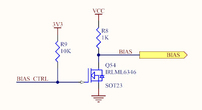
The new track controllers have a little more power in the solenoid activation.  This schematic maybe a little hard to read, but here is the explanation.  The I/O Controller (MCP23S18) is a SPI controller whose outputs are either low or open collector.  The NFET on each solenoid control line is OFF when the MCP23S18 output is low or ON (grounded) when the MCP23S18 output is open-collector.  Previously an auxiliary PIC processor controlled these NFETs directly. Thus the I/O pin on the aux PIC would be either OFF (ground) or ON (3.3VDC).  This ON state did not drive the NFET into full saturation (turn on) and thus there was more (though small) resistance between the SOURCE and DRAIN pins than if the GATE voltage was higher. 


I used the MCP23S18 only because it was the only part available at the time.  But since this forced me into a pullup resistor on every NFET gate, I decided to take advantage of it.  The Gate resistor is connected to a BIAS line.  Using a PIC I/O pin to control another NFET, the bias line is either 5VDC or GROUND.  Thus on Track Controller power up, one of the first items is to set the BIAS_CTRL I/O pin to high, this causes the BIAS output to GROUND, ensuring all of the solenoid outputs are high and the solenoids are not activated.  The pullup on the GATE of Q54 in the schematic below, also ensures that the BIAS output is GROUND while the PIC processor initialization is in progress.  This prevents any solenoid "chatter" during the initialization process, due to the GATE inputs floating.

What else this does is place 5VDC on the GATE of the individual NFET solenoids when they are activated, instead of 3.3VDC in the previous design.  This drives the NFET further into saturation and thus lowers the SOURCE to DRAIN resistance and provides more current to the solenoid.  I have noticed that some track switches seem to be switch faster with the one new controller I have installed.  I need to finish the rest of these and see if that perception is universal.


Thursday, February 23, 2023

Light Buddy2 Working

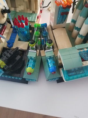
This is a module for the Space Base that is under consideration.  As you can see in the pictures below, this module is still under construction as the Maintenance Men from the station are busily working on the new module.  Here are some more pictures from different angles.

You can see the large MECH that is putting the second Ray Gun as well as the Maintenance Men working on the other section.


A slightly better view of the Large Mech and the Maintenance Men.  In another post to come is explanation of how the power is distributed to this module.  You can see the white wire connecting the module in this picture.

The generator design that started the Light Buddy 2 design and build.

Here is a video of Light buddy 2 working on a new portion of the space base.  I am quite happy how this turned out.  


Wednesday, February 22, 2023

Solar Shed Battery Charging


While I was waiting on the new PCB to come in, I started testing the charging of the battery under real conditions.  What I did was take just the daughter board from the old design (as shown above) and force the path from the solar panel through the LT1085 to the battery.  Then about once a day I recorded the battery voltage to see what was happening.  The data so far is shown here.


There were some very sunny days and a few slightly clouded days.  In retrospect, I probably should have recorded the sky conditions for the previous period also.  The data shows how the voltage has varied.  As a reminder, the solar panel is only 7.5W and has a max current of about 500mA, under ideal sun conditions.  Given the time of year and the fact that sun does not clear the house next door until after 11AM this time of year, I am not surprised that it is not charging very fast.  Once the house next door is not blocking the sun at anytime, which won't happen until sometime in March, I suspect it will be hard to charge much faster.

I am surprised that there appears to be some discharge during the night.  It is not much and for now I am assuming it is more self discharge due to very cold nights (20-25F).  There might be some sneak current path back into the LT1085 when it is not powered.  I did put in a diode in the new desig to help prevent this.


Tuesday, February 21, 2023

Train Work


To make the next step here I need the garage to do some construction work.  In the mean time I am building up more control boards for tracks and lights.  All the controllers work on a Zigbee derivative mesh network (MiWi), which is why I cant use the LEGO controllers.  The light controller uses I2C memory for configuration/script storage (PIC18F47J53 has no internal EEPROM) instead of SPI like everything else.  This is because the LED controller is I2C and the MiWi controller is SPI.  With two MSSP controllers, one for SPI and one for I2C.  The MiWi controller could share the SPI, but then mesh network traffic can get bottled up.  The demand on the I2C network is very sparse.  All of this drove me to refactor the code base to abstract the memory access type.  This was a little more complicated, but I have the I2C working.  Microchip has fairly good DEMO code, but when you start to modify, it is not as stable as you might want.   Plus they #ifdef to the limit, so it will run on every demo board or processor they ever made.

I have been stuck trying to upgrade my train software.   Since I have 4 working controllers and one bridge in the mesh now, things are a little funky.  It all works until the PC asks the bridge to send the configuration data from each controller.  Some 200 pieces of config data plus all the ACKs need to move thru the mesh.  This data exchange is a complete handshake.  The PC sends a very specific request to the bridge,  the bridge sends a message to the specific controller, the controller responds to the bridge, the bridge sends to the PC and the process start over.  I spent days tracking down what was causing it to get way out of sync.  Plus I did lots of code refactoring to eliminate redundant code.  It took two laptops, one connected to the bridge as a controlling link and as a PIC debugger and one connected to a controller to watch message traffic.  After a few days I think what is happening is that the bridge is getting the same message from multiple controllers as the mesh tries to make sure all messages get thru.  At least I am getting the same RF message at the bridge multiple times and then bridge just turns these around and sends them to the PC over USB.  The only way to confirm this is to get another PC and hook up the wireless sniffer and watch all the packets go back and forth.  But I decided to band-aid it so I could move on.   Now I just track the data at the PC, if I already had that piece of data, any repeats were just dropped on the floor  The system initializes properly now, but I got this feeling this will come back at me.

Now I moving on to why some track solenoids don't want to fully activate.  Some of these are 50+ years old, but this is the original "German Engineering" and "Built In West Germany".  My guess is that the FET grounding one side to activate the solenoid is not getting close enough to ground eg, not showing a large enough potential across the coil to get it to move.  I may have to remove the track and rebuild the switches by cleaning the solenoid actuators.


Monday, February 20, 2023

Solar Shed Update


As I explained in the previous post on the Solar Shed, I redesigned the PCB, since the HPC Curiosity Board was consuming too much power.  My plan is to build this in phases (which was a good idea as explained later).  These phases will be and probably in this order:

  • DC-DC converter
  • 3.3 VDC LDO
  • PIC processor, buttons and LEDs
  • LT1085 LDO
  • Relays and FET drivers
  • ADC Input
  • Misc

Once the first three are done, I will work on getting the PIC firmware running.  May have to fake the ADC inputs, but that is OK.  Really all I will be trying to do is ensure the PIC runs and the buttons?LEDs work.  Once that is done, then the rest should go very quickly.

No Power

Following the list above I built the DC-DC converter section.  I literally took the design from the train LED controller, which works, and placed that design on this PCB.  Well there was no 5VDC.   My first thought was that the resistor divider network was in backwards, ie somehow the reference designators had not been placed correctly during PCB layout.  I measured the resistance in circuit, which is always iffy, since there is no way to see what the equivalent circuit really is.  The 20K measured 16K and the 120K, measured 55K.  So I pulled the 120K and replaced it with a 110K, that was in the original design.  Still no 5VDC.

Nothing was getting hot, the converter just wasn't starting.  I poked around with a DVOM looking at the voltages everywhere, other than no output voltage nothing seemed wrong.  Touched up most of the small solder joints, just to make sure they were connected, even though the DVOM showed connections.  Then did continuity checks where I could, still nothing.


Then I carefully looked at the inductor.  These can be hard to get the solder to flow onto the connections.  The picture shows what should be sufficient solder, but these are Lead Free, thus that is silver solder and will need more heat to flow properly.  Plus I didn't help the issue by using the very small tip on the Metcal Soldering Station.  I changed to the bigger tip (see picture below) and reflowed both connections on the inductor.  And that solved the problem😊.  Note to self, don't take short cuts, especially with the inductors and any parts that have silver solder on them already.


Installed the 3.3VDC LDO and the 3.3VDC came right up.  So I am ready to move on and install the PIC processor and related items.

This is why I try to build these in phases.  I have lots of experience building these types of boards by hand, but things happen.


Friday, February 17, 2023

LEGO Shows


Going back to Omaha for Brick Days.  This will be April 22-23 at the Mid-America Center in Council Bluffs IA.  Lets have some fun.  We will be showing the new version of the Space Base in its expanded glory.  

Where else are we going to show.  Well right now that is about it.  Everything else is too far away and not near something we would want to go to.  But we keep looking for events to display at. 


One event that is quite disappointing is Bricks by the Bay will not happen this year.  For whatever reason(s) they have decided to take 2023 off.  This event will be sorely missed.  It was always a great event.


Thursday, February 16, 2023

Android 12 & Delphi 11.2


I finally got around to updating my three Android Apps for API 32/ Android 12.  So to start this blog post off, the following Apps are now available:


T-DUST  is a small module to monitor the  temperature in your Maker projects.  The app provides all the control  functions for a T-Dust device.  This includes displaying in Fahrenheit  or Centigrade, setting the data rate, recording to internal memory and placing the device in the power down collection mode.  The module has a 32Mbit memory on board for recording temperature data.  The app will  chart the temperature data on the mobile device or convert to a CSV file  for download. The module can record for over 120 hours at a 1 second  rate. 


The Power  Monitor is a small monitor module that plugs in between the USB Power Modules and your application.  The USB connection provides a constant  reading of the voltage and current on all of the voltages (12VDC, 5VDC  or VUSB, 3.3VDC, 2.5VDC and 1.8VDC).  The PC program provides all the  control functions and will keep a record of the voltage and current.   The module also has a 32Mbit memory on board for operating in the stand  alone mode.  Power comes from the Port 1 connection.  You can record up  to 65000 records, which is over 18 hours at a 1 second rate.  There is  an optional BT connection for controlling the monitor.  We provide the  API for both USB and BLE so that you can create your own custom  applications.


This is a dedicated brick controller for running your platform  designs. This  controller is dedicated to the task at hand.  Using a simple Android  mobile interface over Bluetooth, the sequence of up to 4 motor  controllers can be setup.  Additionally there are 4 LED lighting control  lines for dramatic lighting effects.  Finally it has three inputs for  sensing different types of real world events.  A Windows PC input setup  is in development and future versions will have an audio amplifier to  provide a single source for controlling your MOC.

Getting here did have some issues.  There were major changes to Android BT permissions.   You can see the changes here. Delphi will automatically generate the Manifest for you based on settings in the Project Options menu.  But this is very basic.  What is needed in some cases, especially Bluetooth implementation, are the qualifiers that go with the manifest entry.

Basically in Android 12 they introduced a SCAN, CONNECT, ADVERTISE permissions and eliminated BLUETOOTH and BT ADMIN.   Though what Google does not say is the ACCESS_FINE_LOCATION permission is not needed anymore, though it was never clear in the docs that it was needed prior to Android 13.  What you need for the basic private BT connection is

<uses-permission android:name="android.permission.BLUETOOTH" android:maxSdkVersion="30" />
<uses-permission android:name="android.permission.BLUETOOTH_ADMIN" android:maxSdkVersion="30" />
<uses-permission android:name="android.permission.BLUETOOTH_SCAN"  android:usesPermissionFlags="neverForLocation" />
<uses-permission android:name="android.permission.BLUETOOTH_CONNECT" />
<uses-permission android:name="android.permission.ACCESS_FINE_LOCATION" android:maxSdkVersion="30" />

 Unfortunately there is no way inside of Delphi to add these qualifiers, ie android:maxSdkVersion=30.  What I did was modify the AndroidManifest_Template to include these lines.  Then in the Project Options men, I made sure these options were deselected.  This way Delphi will not generate these permissions in the android manifest and all will work as expected.  You can find more information about this at the Delphi forums, here.  You may need a guest login to see the thread.


Wednesday, February 15, 2023

Changing of the Colors


When I first started the Space base, I had a general idea of the color scheme, but did not have all the parts in the correct colors.  Using the standard color terms, this is what I envisioned in the beginning:

The base "base" is BLACK.

The majority of the structure is TAN. 

The sturucture accent is SAND GREEN.

The individual section accent is SAND BLUE.

All of the glass is TRANSPARENT LIGHT BLUE

The interior flooring is LIGHT BLUISH GREY

The interior support structure is BLACK

The two BLACKTRON II brigade colors are TRANSPARENT BRIGHT GREEN/LIME (always on the left) and TRANSPARENT DARK BLUE/BLUE (always on the right).

Other colors are used, but are mostly muted colors as to not distract from the above color scheme.

Here are some of the changes that have happened.

This 

has changed to this


this


has changed to this


this

has changed to this, but the two black dishes need to be changed to SAND BLUE.  Unfortunately that color is not prolific and I am waiting on the next collection of parts needed.  That way I can defray the shipping costs, which are only going up right now.


This is the base design.  I have two more to do, since I added the last two sections that make the Space Base a little over a semi circle now.  Usually these designs come to me while I am doing something completely else.