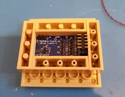
Now that the heresy is completed and the holes are drilled and the LEDs installed, it is time to install the Light Buddy 2.
First step is to attach the 1x1 round plates. The round hite circles on the PCB is where the 1x1 round plates will attach. I use this fixture, which is composed of a 6x6 plate and four 1x4 bricks. I place the 1x1 round plates (orange) in the fixture. Then I carefully add drops of Super Glue on the 1x1 round plates at 90 degree intervals, ie four drops of glue per plate.The PCB is .5mm undersized in both dimensions. So there will be some play when you drop the PCB into the fixture. In this picture you can see the PCB in the fixture. I have installed a surface mount connector in the LED output connector. In this implementation, this how I decided to connect the five LEDs that are used. This gave me the minimum possible height with the LED connector installed.
NOTE
In very small/tight installations, you may choose not to have the LED connector installed and just solder the wires into the solder pads for the LED connector.
Here is the PCB in the fixture. You need to leave it in the fixture long enough for the glue to setup. I use a small screw driver to lift each 1x1 round plate from the 6x6 plate when I remove it the first time. Because of the small surface mount connector. I left the most margin on the left side.
Here is it what it looks like after removing from the fixture.
To solder the wires onto the connector, I used a scrap plate (in this case 6x8) that I attached the Light Buddy 2 to. This way I don't have to chase the PCB when soldering.
Here is what the installation looks like once the wires are soldered to the connector and the Light Buddy 2 is placed in the bottom Power Generator.
This shows the next issue that needs to be fixed. I had to leave a reasonable extra length of wire as a service loop. This was especially true for the LED on the top. But now where to put this extra wire so it does not get in the way when installing the Power Generator into the MOC.
I built these small L shaped pieces out of two 1x1 plates and one 1x2 plate. This allows for a gap for the wires to be coiled up into. This picture shows the final configuration of the Light Buddy 2 in the bottom of the Power Generator. The only wires coming out are for the 5VDC power that powers the entire device.
While this was not necessarily planned, the 3 pin connector that is the RS-232 interface to the Light Buddy 2 for the PC program is usable. You can see it in the lower right portion of the PCB. This gives the ability to reprogram the LED's for different styles if needed.


No comments:
Post a Comment