Showing posts with label PIC16F18326. Show all posts

Monday, August 14, 2023

MPLAB and XC8 - A Tale of Woe

Where I have been for the last week or so, on another barefoot journey across a LEGO pile with MPLAB and XC8 compiler.  Bottom line,  beware of C compilers claiming improved performance.

My very small Light Controller was depending on the 256 bytes in the EEPROM for config and script storage.  After config storage, that left about 220 bytes for the scripting.  But each LED takes 5 bytes to describe the time, command, state, features and PWM setting.  So a single time slot with all 6 LEDs changing can take 30 bytes.  Thus in 7 time slots all the memory can be used.  I had over 4K left in flash, so I decided to move the scripting there.  I had done this in one of the PIC32s that did not have EEPROM.

And the fun begins.  Harmony in the PIC32 had libraries for doing this, it was fairly easy.  I had written a boot loader for an older PIC, so this cant be that hard.  Well after 3 days on and off trying to make this work, I decided to change course.  Brand new MPLAB project with only the FLASH writing routines and using the MPLAB Code Configurator to generate the FLASH routines.  Their routines were essentially the same as what I wrote.  I could not see any difference that would make it work over what I had done.

But this did not work either.  I spent a huge amount of time trying to debug this with no change.  Then I spent a day reading every FLASH routine posting I could find.  90%+ were using the MCC routines I had generated.  Most problems were related to other things that I had already implemented.  Then I finally found one post where the person could not get FLASH to work.  Microchip told  him to change compilers.  There was an issue in 2.35 and that 2.36 fixed that.  Well 2.36 was a transitory release and I had a choice between 2.40 and 2.41.  Knowing that x.x0 and x.x5 is Microchips release schedule and any other numbers are bug fixes, I went with 2.41.  And what do you know, the dedicated program started writing to the FLASH.

Could it be that simple, of course not.  Compiled the Light Controller and it still failed.  Now to be fair I had slightly rearranged the MCC generated code to fit my overall structure.  So I went back to the dedicated program and pointed all the FLASH routines at my revised code.   Also renamed all the FLASH routines in this dedicated program directory so there was no way they would be included.  And it works just fine.  I then made sure the configuration bits were the same in both programs.  The last thing I did was copy the oscillator startup code from the Light Controller to the dedicated program.  Still works.

Startup code, project properties, compiler settings were the first things to look at and these were all the same.  Something in the startup code?  I cut out the test routine of the dedicated program and placed it as far in the front as possible.  Still would not work.  At this point almost a week has gone by and I am getting no where.  I have been taking breaks to work on other things, one to clear my mind and two to have some sense of progress. 

At some point I remembered some quirky things I had read about EEPROM unlock sequence.  Back to the dedicated program to trace through the assembly code to see how that worked.  The unlock sequence is 0x55 then 0xAA then set the write bit.  The green is the C code and the rest is assembly.  Nothing exciting here, what I would expect.

Then to trace through the Light Controller.  Both are using the exact same code base, there is no difference, no #ifdef, no changes at all.  There are two differences, either of which could cause a problem. Line #187, the BANK command.  Why is that there, that should have been before the sequence started.  Then the real problem is Line #193, another BANK command and inserted just before the write bit.  My understanding is that the unlock sequence is timed and set for exactly 5 instructions.  At a minimum, setting the write bit has to be the next instruction after loading 0xAA.

After some more reading I came up with this assembly code sequence for the unlock.  The C code using inline assembly is in green.  As you can see the generated instructions are exactly 5 instructions long and it works as expected.  

So after a week of messing around with this, it finally works.  I will probably go back and replace the unlock sequence elsewhere with this assembly version, just to make sure that somewhere in the future the compiler doesn't change it's mind and change the C code.


Thursday, February 23, 2023

Light Buddy2 Working

This is a module for the Space Base that is under consideration.  As you can see in the pictures below, this module is still under construction as the Maintenance Men from the station are busily working on the new module.  Here are some more pictures from different angles.

You can see the large MECH that is putting the second Ray Gun as well as the Maintenance Men working on the other section.


A slightly better view of the Large Mech and the Maintenance Men.  In another post to come is explanation of how the power is distributed to this module.  You can see the white wire connecting the module in this picture.

The generator design that started the Light Buddy 2 design and build.

Here is a video of Light buddy 2 working on a new portion of the space base.  I am quite happy how this turned out.  


Friday, February 10, 2023

Installing Light Buddy 2 - Part 3


Now that the heresy is completed and the holes are drilled and the LEDs installed, it is time to install the Light Buddy 2.  

First step is to attach the 1x1 round plates.  The round hite circles on the PCB is where the 1x1 round plates will attach.  I use this fixture, which is composed of a 6x6 plate and four 1x4 bricks.  I place the 1x1 round plates (orange) in the fixture.  Then I carefully add drops of Super Glue on the 1x1 round plates at 90 degree intervals, ie four drops of glue per plate.  

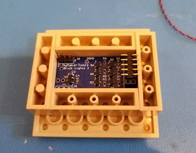
The PCB is .5mm undersized in both dimensions.  So there will be some play when you drop the PCB into the fixture.  In this picture you can see the PCB in the fixture.  I have installed a surface mount connector in the LED output connector.  In this implementation, this how I decided to connect the five LEDs that are used.  This gave me the minimum possible height with the LED connector installed. 

NOTE

In very small/tight installations, you may choose not to have the LED connector installed and just solder the wires into the solder pads for the LED connector.

Here is the PCB in the fixture.  You need to leave it in the fixture long enough for the glue to setup.  I use a small screw driver to lift each 1x1 round plate from the 6x6 plate when I remove it the first time.  Because of the small surface mount connector. I left the most margin on the left side.

Here is it what it looks like after removing from the fixture.


To solder the wires onto the connector, I used a scrap plate (in this case 6x8) that I attached the Light Buddy 2 to.  This way I don't have to chase the PCB when soldering.

Here is what the installation looks like once the wires are soldered to the connector and the Light Buddy 2 is placed in the bottom Power Generator.

This shows the next issue that needs to be fixed.  I had to leave a reasonable extra length of wire as a service loop.  This was especially true for the LED on the top.  But now where to put this extra wire so it does not get in the way when installing the Power Generator into the MOC.

I built these small L shaped pieces out of two 1x1 plates and one 1x2 plate.  This allows for a gap for the wires to be coiled up into.  This picture shows the final configuration of the Light Buddy 2 in the bottom of the Power Generator.  The only wires coming out are for the 5VDC power that powers the entire device.

While this was not necessarily planned, the 3 pin connector that is the RS-232 interface to the Light Buddy 2 for the PC program is usable.  You can see it in the lower right portion of the PCB.  This gives the ability to reprogram the LED's for different styles if needed.


Thursday, February 9, 2023

Installing Light Buddy 2 - Part 2


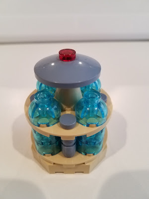
Now I need to place the LED's and the wiring.  First I need to change the sand blue 1x1 round tile to one that is transparent red, as shown here.

But between the size of the dish and the hole that had to be drawn, the 1x1 round tile will not fit.  You can see that from this picture.

What I need is an extension.  My first thought was a 1x1 round brick as shown here.

But as you can see not much light is coming through.  My next thought was a 1x1 round plate with an open stud.  But the only transparent ones I had were light blue and I really wanted red.I checked Bricklink and while it said they existed, the number of stores that had them was 3.  Not a good probability of getting them.  The only other transparent color that was a possibility besides light blue was orange and that did not appeal to me.  So I thought that by reducing the distance from the LED to the transparent 1x1 round tile, maybe that would help.  That led to this, which is similar to the 1x1 round plate with open stud.

While it is brighter, it is really only visible if you are looking straight down on it.  Looking closer at this arrangement, I see that the lip on the 2x2 dish is blocking the LED light, forcing it straight up.  That realization led to the final configuration.

The transparent red 2x2 dish and the 1x1 round tile are both lighting up.  This is the effect I wanted.  The wiring now runs down the 2x2x2 cone with open stud, through the center hole of the 6x6 round plate into the cavity where the Light Buddy 2 will be.

Placing the four LEDs under the 2x2 round transparent light blue bricks was fairly easy.  The wiring is small enough that it will run under the 2x2 round brick or through the gap in the side where it fits on a stud on the 6x6 plate.  It then follows the wiring from the top through the hole in the center of the 6x6 round plate and into the cavity below.


Next step is to connect the wiring up to the Light Buddy 2 and place it in the cavity.


Wednesday, February 8, 2023

Installing Light Buddy 2 - Part 1


While the firmware is not yet complete, I went ahead and started building the first instance of this new LED Controller.  

This requires doing something that is controversial in the LEGO community and that is modifying the bricks.  My take is that drilling holes for wiring or letting LED light though, when no other option is possible and this holes cannot be seen, is acceptable.  Modifying bricks for an artistic effect is pushing this idea too far for me.

The first modification is the sand blue dish on the top.  In the build, the sand blue 1 x 1 round tile on the top will be replaced by a transparent red tile, so that that a glowing LED can be placed there.  There is no open stud in this part, so I will need to drill a hole for the wires.

The next two pictures show the problem.  First the hole has to leave the surrounding shoulder plastic so that the tan cone has something to connect to.  Second, in this configuration the dish is not stable.  Attempting to drill in this manner will likely result in the dish tilting and the hole not being where I wanted it.


The solution is to use 1x1 round plate with an open stud.  This picture shows that I have chosen a drill bit that will just fit into the open stud.


By placing the 1x1 round plate on the dish, it will serve as a drill guide.  The dish is now facing down and in the most stable position.  This makes drilling the hole very easy.

And here is the result.

The generator LED's are placed at the bottom of the 2x2 round transparent light blue bricks.  But the 6x6 round tan plate will not the LED light up into the 2x2 round domes on the 6x6 tan plate.  Here is where major modifications are needed.  The 6x6 tan plate has a hole in the center which will be needed for the wires coming down from the top of the dish.  Thus I need to drill holes of the same size where the center of the 2x2 round bricks attach.

There are two approaches to this. 

Drill from the bottom.  But as this picture shows, the location of the holes is not a normal circle.  That odd shape will cause the drill bit to wander and force the part to move unless it is tightly clamped down.

Drill from the top.   This approach is easier, but there does not exist a natural drill guide.  I would be guessing where the center is.  Thus as with the dish drill above, I am using a 2x2 round tile with a hole in the center.  This places the hole exactly where I want it.


Here is the 6x6 round plate with the four additional holes in it.

Next installment will be installing the LEDs.


Tuesday, February 7, 2023

LIght Buddy 2 - The Build Part 2


After spending the AM looking into this, I finally found the problem.  It is and isn't my new PCB.  Above is a photo of the setup.

The absolute source of the issue is the USB battery.  But it is only doing what it was designed to do.  All USB batteries have a minimal current flow cutoff circuit designed into them with a timeout delay.   When the current drops below a preset limit, the battery turns off after the delay.  This minimizes the self discharge rate.  The silver battery in the picture is the one I use for development because it seemed to have a very low cutoff, as in it doesnt turn of as long as something is plugged in.  The LED lights indicating current charge level never went out.  Other USB batteries I have require at least two devices connected with motors and LEDs active, to stay on.  And when they shut off, they shut off completely.  But when I connected the Analog Discovery to the PCB, I found this.

Sometimes the dropout is deeper,  down to just under 2VDC and varies in time from this to about 20ms.  It also happens every 27-28 seconds, which is probably the batteries timeout.  When I switched the power source to a wall charger, all of this went away and the debugger worked without failure for over 30 minutes.  Final test was to add a 100 OHM resistor load to the USB battery using the USB power connector (PCB with red and white punch down blocks on it).  Worked the same as the wall charger.  Removing the 100 ohm resistor and it reverts back to resetting every 27-28 seconds.  

My PCB just did not draw enough current to keep the battery happy.  The USB battery would start to shutdown the voltage, the PCB would start to draw more current as the voltage decreased.  This increase in current was just enough to restart the battery.  Rinse and repeat.
 

Monday, February 6, 2023

MIcrochip PICKIT 4 Not the Problem


I use the Tag-Connect 6 pin connector with Pogo Pins.  Very small footprint.  It appears that the one I have been using for a long while is now flaky, which is why the PICKIT 4 would not connect.  I had another one, but it only had an RJ-11 connector, so I went digging for my ICD3.  Fortunately the ICD3 will do at least two of the four processors I have chosen.  So I thought I would look at buying an ICD4, just to be current.  Well it is EOL, happened back in late September.  The forums seem to indicate they could not build any more, no parts.  In particular no FPGAs are available at an acceptable price.  So that leaves an ICE4 @ $1800 or PICkit4 which I have.  I just might have to buy another PICKIT 4 for insurance purposes.  I did look on Ebay for an ICD4, none to be found and the Asian market wants $1950.  Digikey, Mouser, Newark, etc have all pulled the listing as obsolete.  The Microchip website claims they will continue to update the programmer.  This has only solved my connection problem, the BOR problem still exists as does the debugger resetting when in debug mode.

For older PICs, theICD3 and PICKIT 3 are adequate, not as many breakpoints, but otherwise mostly equivalent.   ICD3 and PICkit3 are not getting any new PICs added to them, so these two will only be the older PICs going forward.  Ends up being the two most likely candidates, PIC16F18326 and PIC16F18426, are old enough that ICD3 and PICkit3 will work on them.  The only issue that will push me to the other two PICs (PIC18F06Q40 and PIC18F06Q41) will be execution speed.  The PIC16F runs at 32MHz and the PIC18F runs at 64MHz.  PIC power is not the issue here, with 6 LEDs running at 25mA each. The power difference is 3mA vs 13mA.  So 10mA increase which leads to 153mA vs 163mA in total power, 6.5%.  I can live with that.  And if the LEDs use less current, say 5mA each,  Then its 33mA vs 43mA, 30% increase.  But the total power is down 73%.  All good.

Tomorrow I am going to try and track down the Brown Out Reset issue, because now I am convinced that is also resetting the PICkit/ICD in debug mode.


Friday, February 3, 2023

Light Buddy 2 - Build Part 1


Part of the development time was me copying code from the PIC32 project and not getting all the code.   Then there was a mismatch in the com protocol between the PC and the PIC that had to be fixed. Again, all for the good as I develop a lot more consistent interface and infrastructure code across all of my projects.

When I moved to the PCB two things started happening that were not present on the Microchip Curiosity Development Board.  I could not buy PIC16F18326 parts and had to settle for the LF version.  Should be NO big deal, though it did force the LDO decision to a 3.3VDC version.  First every few seconds the Brown out Reset would fire.  Added code to print out the the registers that tell you what caused the reset, so I know that was it.   Once I disabled BOR, that quit happening.  But now I dont know if what the PIC was seeing is not causing other issues.  

Second the PICKIT 4 is unreliable, not sure why yet.Part of it was a poor connection to the board.  I fixed that, but it will still reset it self after a few seconds.  This is probably related to the BOR issue, just not sure how to debug this, especially if the drop out is very narrow.  Also had to upgrade XC8 and MPLAB X to 5.5, which means the 64bit version.  But as the picture shows I moved to an ICD3 to continue working.

While this PIC runs at 32MHZ max, I am pushing it when running all six LEDs in full feature mode.  I can tell the service loop is not getting around as fast by the way the LEDs react.  It may be OK, I just need more time to refine the loop.  The loop is every 100msec and that may not be enough time to service 6 LEDs.  Also the free compiler does not do a great job on speed optimization.

As an aside, several people have suggested using switches to select the LED modes.  I passed on the switches for now.  The serial port makes it much easier to develop the lighting features and provides a console feature for printf.  Though I had to finish the PC program first before I could get started on the PIC firmware.  Every time I add new features to this Windows software, the whole structure of the program slightly mutates, thus more testing for older features to make sure I did not break them.   The software is getting more structured and easier to modify, just takes time.

Wednesday, February 1, 2023

Light Buddy 2 -The PCB

I received the REV 1 PCBs.  As you can see, they are exactly the size I wanted.  This picture below shows the PCB in the base of Power Generator design I am working on.  I had to extend the height with a 3 x 3 Modified Facet Brick.  That should give all the height I need.  Will probably turn the PCB over and attached the round plates and then mount the PCB to the round plate.  I can always add more 1 x 1 round plates to increase any spacing I need.  So far I am very happy with this.


In the mean time I have been working on the software.  Here I am using a Microchip Curiosity LPC Development board (P/N DM164137) with a PIC16F18326.

Most of the code came together rather quickly.  As I mentioned in the previous posts, this PCB can use 4 different PICs (PIC16F18326, PIC16F18426, PIC18F06Q40 or PIC18F06Q40).  My recent experience with lack of availability drove me to this.  But I wanted one piece of firmware.  Thus I have been experiencing the joy of #IFDEF.......#ENDIF.  I have actually spent quite a bit time with the development board and two of the PICs building the app.  Since these 4 PICs span a few years of introduction, the consistency on the peripheral naming is not great.   I finally have the first two in the above list working at the 95% completion point, the other two are about at the %60 point.  But the last two in the above list should come up quickly since most of the infrastructure is there.  I will have to move to a newer XC8 compiler and newer version of MPLAB X, though to finish up with those newer PICs.

Just as an aside, sometime in the last few years, Tech Writing at Microchip under went some changes.  The datasheets are laid out a little differently now.  I am using PICs that have dedicated PWM controllers in addition to the normal CCP/PWM modules.  On the PICs the CCPs are numbered  1 to 4 like normal.  But the PWMs are number 5&6 on one PIC and 6&7 on another.  The Timers names are different as are the UARTs.  I ended  up with lots of #IFDEF to handle this, including an additional system type 'h' file, because there was some circular reference driving the compiler to spit all kinds of weird errors.

Since this is an old fashion RS232 interface, I had to resurrect some very old code.  For all of my PC LEGO control, I am trying to use one windows APP.  In the USB HID world this proved to be quite easy since identification is built into the USB HID protocol.  The WIN APP then just determines who just connected and adjust accordingly.  Well plugging in an RS232 device that stuff doesn't happen.  You have to code it.   Integrating this into the existing code was not hard, just time consuming.  Surprisingly some remnants of old RS232 interfaces were still present in some of the code.  Dont think I have started form scratch in a long time.

I am fairly close to building a few and testing.  While these do not have a remote control feature, in some cases hiding it in something small is advantageous.

I am now wondering if I can make a smaller one😋


Monday, January 30, 2023

Light Buddy 2 - The Design


Here is what the board looks like.  It is very simple, just a fancy way to control 6 LEDs to produce fixed (kind of) lighting effects.  No remote of any kind.

The voltage regulator, U2, will take up 16VDC and produce either 3.3VDC or 5VDC, haven't decided what voltage to run at.  The intended input is VUSB, so if it is 5VDC, it will just follow the input.  J9 is the power input (GND-VUSB-GND to help prevent incorrect connections).

J8 is a standard TTL/CMOS level RS-232 interface.  My intent is to allow the 6 outputs to be programmed in some fashion, TBD.  The problem is anyone who does this will need a RS232 to USB converter.  For me, this not a big deal, for some LEGO users, this may be a bridge to far.   So when you order it, I would program with the desired effects.  The buyer would pick from a selection of choices.  I have also considered a BT module that plugs onto J8 and J9.  Then you would use the Light Buddy Android App to update it.

The remaining parts are six N-FETs to drive the LEDs and protect the processor outputs from excessive current draw.


On the backside, the two circles is where small 1 x 1 round LEGO plates will attach to the PCB (super glue).  This allows the board to be mounted into the LEGO Model.

The processor is either PIC16F18326, PIC16F18346, PIC18F06Q40 or PIC18F06Q41 families.  They come in different memory sizes, I always start with the largest until I figure out how much I really need.

Finally, the absolute bane of my existence, connectors.  All of these are of the 2mm type.  But as you can see they are large compared to the board.  I have used smaller 1mm 2 pin connectors before, but they are very difficult to un-mate.  Everyone complains about them.  Obviously J8 doesn't need to be populated unless you intend on using the RS232 interface.  J9 could be soldered in.  That just leaves J1 for the LEDs.  They also could be soldered in, but that would make working with the LEGO model more difficult.  You should be able to plug in individual 2 pin 2mm male connectors into J1 for each LED.  I keep looking for a solution to this problem, but have not found anything yet.


Thursday, January 26, 2023

Light Buddy 2 - The Need


I have been working on a LEGO generator design for the large LEGO display.  I needed at least 5 LEDs.  4 of them generate a pulsating electric thingee, kind of like a lightning effect or an arc welding effect.  I do this with a PWM generator and then randomly change the times and pulse width.  Not perfect but it does a good job.   I needed this to be small and with some new PICs that have multiple PWMs and independent timers, I think I can get this down to a the size of a 2x4 Lego brick (15.5 x 31.25mm), although it is two sided.  The PIC controllers I am looking at are PIC16F18326, PIC16F18426, PIC18F06Q40 and PIC18F06Q41.  These are the large memory versions.  Once the code size is determined, may be able to move to smaller memory versions.  This will just give more flexibility in ordering, considering the state of IC availability has only marginally improved.

The amazing part was that the PCB vendor I am using for PCBs (PCBWAY) is selling  2 layer, 10 pieces for $5 total, $23 in shipping and 24 hour turn if in green, any other color is 5-6 days.  At those prices it is almost not worth wiring a manual proto anymore.  Could build some generic proto boards to play with.  The max size appears to be 100x100mm or just under 4x4".  And if I were to do multiple designs, the cost would be less since they will all fit in a single package.
 

This may be the next LED controller.