Thursday, August 31, 2023

Brick Fest Live San Diego - Day One

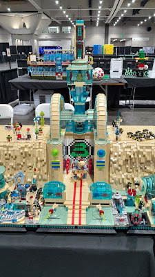
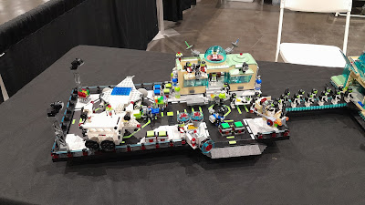
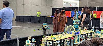
This was a very large crowd, much larger than San Jose.  It was a great time.  First off a series of pictures of the display as it was finished.


Yesterday I showed some pictures of detailing.  Well some minor changes were made.


We might be getting carried away here.

There were lots of questions, especially from the smaller group.  Some wanted to know how they supervisors were drinking coffee and eating doughnuts without oxygen.  How come the guys on the stretchers did not have helmets.  How did the Nebraska chicken get there.

Here are some of the other attractions at the show.


You just knew that this was going to be spread out over every where.


This was the white brick build.  

The display is actually 360 degrees.  That is there is just as much happening on the backside as the front.  Every once in a while we would let people who showed extreme interest into the displayer's area so they could take pictures.

Finally here is a quick video of the entire display.  I really need to get a steady cam.  I can solder 0603 resistors with ease, but hold the camera steady, not a chance.


Wednesday, August 30, 2023

Brick Fest Live San Diego - Setup


 It is setup day at Brick Fest Live in San Diego.  Setup started at Noon and we had to be done by 5PM.  In the past this has taken about 3.5 hours, however there is a small amount more.

The biggest issue is where the table split will fall.  In San Jose I moved the split to the right of the center in the middle of the module to the right.  We will see how that works out.


The San Diego Convention hall is much bigger than San Jose.  
 
 
There are 19 storage bins to hold the MOC and the support tools.
 
 
I started on the far right with the new floating platform and then moved to the left.

 
At this point I have 4 modules assembled.  I connect all of the power wiring as a module is assembled.  Then test to make sure the lights work.  Assembly the entire display and then testing would be OK if it all worked, but that never happens.

 
Here is the center module.

 
And with all the pieces that make up the entire center.

 
The long view.


These pictures were all about positioning the center module in preparation to connect it tot the modules to the left.

 
They needed to go somewhere.


After some coercion, the center connects to the modules to the left.  There are 5 Technic pins that have to connect.  Lining them up can be challenging.
 
 
With the center module connected, we can see where the table split is.  Not ideal, but we see how it goes.

 
Done through the center plus one.  Time so far is about one hour and 45 minutes.

 
Once all the modules were connected, then I could connect the floating platform.

 
A view to the left.

 
Some of the detailing that goes on.

 
A view from the back.

 
All done.

 
This time it took just under four hours from the time we checked in to ready to leave.  This includes three trips from the basement garage to the convention hall.  It could go faster and I am always looking for ways to make it go faster.

Tomorrow is day one.

Wednesday, August 23, 2023

Brick Fest Live San Diego - Begins


Since I mostly got around the XC8/MPLAB problem I was having, I have spent the time getting ready for Brick Fest Live San Diego.  The last time we were there was in Nov 2021 and it was actually in Del Mar.  This year it is at the convention center down town.  This where Comic Con is every year.  

I finished the updating the Space Port and floating platform as far as it was going in this round.  The space port was converted to a Brick Buddy 3 controller that is buried in the base, instead of a huge Brick Buddy 1 on the outside.  Also modified the back side for the eventual connection to a tunnel into the mountain.

The other important item I finished was a new electrical connection method using the old 9V Black motor connectors.  This is now used to power the Maintenance Shed.  It cannot be attached during transport, so I needed a simple way for this to work.  I intend to use this method for the large mast lights on the floating platform also.

After the show, I will be writing up several posts on the space Port Conversion, the Maintenance Shed and the new electrical connection methodology.  

More info on Brick Fest once we get to San Diego and start setting up.


Monday, August 14, 2023

MPLAB and XC8 - A Tale of Woe

Where I have been for the last week or so, on another barefoot journey across a LEGO pile with MPLAB and XC8 compiler.  Bottom line,  beware of C compilers claiming improved performance.

My very small Light Controller was depending on the 256 bytes in the EEPROM for config and script storage.  After config storage, that left about 220 bytes for the scripting.  But each LED takes 5 bytes to describe the time, command, state, features and PWM setting.  So a single time slot with all 6 LEDs changing can take 30 bytes.  Thus in 7 time slots all the memory can be used.  I had over 4K left in flash, so I decided to move the scripting there.  I had done this in one of the PIC32s that did not have EEPROM.

And the fun begins.  Harmony in the PIC32 had libraries for doing this, it was fairly easy.  I had written a boot loader for an older PIC, so this cant be that hard.  Well after 3 days on and off trying to make this work, I decided to change course.  Brand new MPLAB project with only the FLASH writing routines and using the MPLAB Code Configurator to generate the FLASH routines.  Their routines were essentially the same as what I wrote.  I could not see any difference that would make it work over what I had done.

But this did not work either.  I spent a huge amount of time trying to debug this with no change.  Then I spent a day reading every FLASH routine posting I could find.  90%+ were using the MCC routines I had generated.  Most problems were related to other things that I had already implemented.  Then I finally found one post where the person could not get FLASH to work.  Microchip told  him to change compilers.  There was an issue in 2.35 and that 2.36 fixed that.  Well 2.36 was a transitory release and I had a choice between 2.40 and 2.41.  Knowing that x.x0 and x.x5 is Microchips release schedule and any other numbers are bug fixes, I went with 2.41.  And what do you know, the dedicated program started writing to the FLASH.

Could it be that simple, of course not.  Compiled the Light Controller and it still failed.  Now to be fair I had slightly rearranged the MCC generated code to fit my overall structure.  So I went back to the dedicated program and pointed all the FLASH routines at my revised code.   Also renamed all the FLASH routines in this dedicated program directory so there was no way they would be included.  And it works just fine.  I then made sure the configuration bits were the same in both programs.  The last thing I did was copy the oscillator startup code from the Light Controller to the dedicated program.  Still works.

Startup code, project properties, compiler settings were the first things to look at and these were all the same.  Something in the startup code?  I cut out the test routine of the dedicated program and placed it as far in the front as possible.  Still would not work.  At this point almost a week has gone by and I am getting no where.  I have been taking breaks to work on other things, one to clear my mind and two to have some sense of progress. 

At some point I remembered some quirky things I had read about EEPROM unlock sequence.  Back to the dedicated program to trace through the assembly code to see how that worked.  The unlock sequence is 0x55 then 0xAA then set the write bit.  The green is the C code and the rest is assembly.  Nothing exciting here, what I would expect.

Then to trace through the Light Controller.  Both are using the exact same code base, there is no difference, no #ifdef, no changes at all.  There are two differences, either of which could cause a problem. Line #187, the BANK command.  Why is that there, that should have been before the sequence started.  Then the real problem is Line #193, another BANK command and inserted just before the write bit.  My understanding is that the unlock sequence is timed and set for exactly 5 instructions.  At a minimum, setting the write bit has to be the next instruction after loading 0xAA.

After some more reading I came up with this assembly code sequence for the unlock.  The C code using inline assembly is in green.  As you can see the generated instructions are exactly 5 instructions long and it works as expected.  

So after a week of messing around with this, it finally works.  I will probably go back and replace the unlock sequence elsewhere with this assembly version, just to make sure that somewhere in the future the compiler doesn't change it's mind and change the C code.


Friday, August 4, 2023

Antenna Care


 Here is the issue.  This Antenna (Part Number 2569) is fairly rare and thus expensive.  Prices in the US start at $4.00, while the black version starts at $0.01.  These parts can bend very easily if not stored properly.  I have had the solid color version (red, black yellow) have minor bending when a large number are all placed in single bin.  Thus I am concerned about how to store these.

I started with these two ideas. 

The ball at the end of antenna barely fits through the 1/2 length Technic pin.  Antenna removal required removing the the three 1x2 Technic Brick with Holes.  Removing the bricks was not easy and would often stress the antenna as the ball tried to pass through the Technic pin. 

Next I removed the Technic pin.  Now there is ample room for the ball end of the antenna to slide through the Technic Brick.  But Technic Brick would still be hard to remove and then the sudden break of the brick connection would again put stress on the antenna.


Which led to this implementation.  There are 1x8 Technic Bricks with Holes on each end.  Each 1x8 brick has the 1/2 pins inserted.  The antenna is inserted from one end.  Some minor pressure is exerted to make the ball end pass through the 1/2 pin on the other end, but it is very minor to none.

This shows the other end.  With a 8x10 plate arrangement (combined 6x8 and 4x8) the entire antenna is captured.

I noticed some flexing of the built up 8x10 plate.  I changed the arrangement to have three 1x10 bricks across the bottom to give it structure. 

This is the final version.  I noticed that when I reached three bricks high on the 1x8 Technic Bricks, they started to lean in or out.  So I placed a 6x10 plate every two high.  I also changed up the end the antenna is inserted, to make removal easier.  So far it seems to work.  

As long as I can keep direct sun and excessive heat, this should work.