Friday, November 24, 2023

Loose Ends #1


 I am starting a continuous series of posts of just small items.  Things that do not merit a full blog post by themselves, but are none the less interesting.

Sorting through a Bricklink order.  This can take a while depending on the size of the order.  I still continue to spend at least 20% of my build time, sorting and storing bricks.  Either ones I just bought or cleaning up after a build session.

The beginnings of the shower facility next to the gym.  Still needs the white round tiles for floor tiling.  The area to the left will be a soaking tub.  The area to the right will be the changing room.


The hanger that connects to the dining/gym/recreation area is getting a partial glass partition.  Instead of the open type it was before.  It would be nice to come up with a door of some type for the lower section.  Also not sure about the color scheme here.  I am thinking that the light blokish gray brick and the tan support needs to be black.  Just not sure yet.

This is where the Kitchen/serving area will be.  There will be four large menu screens.  The four areas will be appetizers, main course, desert and drinks.  It is not a huge space, but is buried towards the back, so it will look larger than it really is.

And that is all for now.


Tuesday, November 21, 2023

Left Side Connector


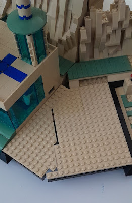
This is the left side connector.  This is the largest platform connector in the display.  Relatively speaking, it is a large surface area.  Thus building a normal power scheme or control area just did not seem to be the correct choice.

And as a reminder, this is the normal type of connection.  My first thought was to build some kind of a loading area for cargo.  The downside to this idea is that there is no real entrance for the material.  It could be a temporary storage area.  


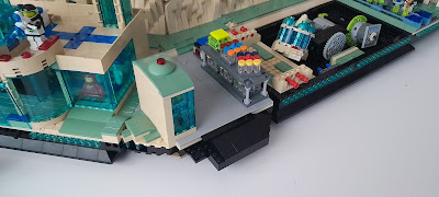
This was mostly just covering the left side with sand green tiles and the remainder with light bluish grey tiles to represent the armor plating.  Then I built a small maintenance shack and rack to store pallets. This picture and the ones that follow show this.  It also include a ramp area for  loading and a stair case to the walkway around the display.

 
The first visual that I saw was the back to the shack.  It just stuck out at me.  It did not fit into the scheme at all.
 

So I swapped the two structures like this.  It is better, but still not good. 

Like the right side, this is something I will have to come back and revisit.  


Monday, November 20, 2023

Right Side Connector


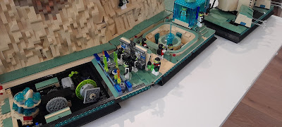
 This is first connector I am working on.  This shows the blank and the equivalent in previous connectors.  My first thought was a large control panel on one side and some form of power system that the control panel is monitoring.

I built a stand with SNOT bricks.  Then attached a 6 x 10 plate.  On the upper 4 x 10 section of studs,  I attached various decorated tiles.  On the top row,  I used decorated 1 x 2 "cheese" slopes, except they are facing down.  One row up from the bottom, I attached two 1 x 4 SNOT bricks to form a shelf.  Then placed more decorated tiles. 

Here is a close up of the control panel.

I went through multiple iterations of the power system.  The space is essentially 4 x18 studs. This shows one of the iterations.

This is where I ended up.  I am not particularly happy with this.  It is OK, but not what I was hoping for.  I can always come back and change this later.  Though I have some really small UV LEDs and if I can get them under the four antennas and the four cones (all transparent neon green), then this might look pretty good.

Here it is installed.


Sunday, November 19, 2023

Curved Cliff - Part 6


 Moving on to the rock work.  

The long view.

A closer view.  The right side angle portion has been integrated into the straight section.  The left side is still separate.  This is because adding the left side will not allow the cliff to fit into the standard shipping box.

I added some striations of color into this one.  A combination of dark tan and medium nougat. 

This is the finished version of the right and center section.

This shows the left side support structure completed.

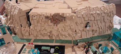
Finally a sweep from left to right of the finished rock face.


You can see the line where the right and left side mate to the next cliff module.  Unlike when to straight modular sections meet and the line can be hidden, this is not the case here.  I did do some 90 degree turns of the slope pieces.  Also because of the way the structure behind the rock face is done, this cliff face does not slope as much.  The difference is slight, but I can see it.


Saturday, November 18, 2023

Curved Cliff - Part 5


 Progress is a relative term.  Testing positive for COVID on Monday has slowed things down somewhat.  While this is a very mild case, working has been challenging.  Because the second level ended up on the wrong level, it was one brick height too high, and because I wanted to integrate the right side angle piece into the main section, I started over.  This picture shows what was stripped back.

This shows the backside and where the second level will end up.

First task is to make sure the wiring is in place.  I am using the 1 x 2 brick with a vertical groove in it.  Also when the electrical is just power, (on/off vs actual lighting features) I am using the ribbon cable version of the 30 gauge silicone wire.  You can get this wire here.

I used a 1 x 2 Technic brick to pass the wire up from the bottom.  The vertical groove is large enough for the wire to pass through with only one side.  That is you do not need to create a larger hole by placing two bricks back to back.  The problem with this is approach is that this creates a 1 x2 brick stack that is only secured at the bottom and the top.


As these two pictures show, a few times I did use two bricks back to back, but they are rotated 90 degrees to lock the stack into the wall. Takes more 1 x 2 brick with vertical groove, but provides more stability. 

At the top is another 1 x 2 Technic brick to pass a wire to the front side.  This wire will be used to light up the second floor.  The wire will have to be concealed behind the rock work.

At the top of the first floor the wire needs to run along the ceiling.  Using 1 x 1 round plates, I can thread the wire through the gaps in the 1 x 1 round plate stack.

This picture shows a closeup of how the wire is routed through the 1 x 1 round plate stack.  

Now on the other side as the wire runs up the rock face side to the second floor ceiling.  This starts as a 1 x 2 space for the 1 x 2 brick with vertical groove.  Then it is reduced to a 1 x 1 space and I use a 1 x 1 round brick.  The wire runs in the space left by the 1 x 1 round brick.  At the top it goes through the wall at the top through a 1 x 2 Technic brick.

This methodology continues up the rock face until we get near the top.  This picture shows the rock work just as we reach within one brick height.  The wire is running through the space created by the round brick.  I had to put one 1 x 1 round plate to level the right side off.  Then a 1 x 2 inverted slope is needed to level the left side.  Also the inverted slope is needed to create the space for the final 1 x 2 brick with vertical groove. 

This picture show the 1 x 2 brick with vertical groove in place and the wire passing through the 1 x 2 Technic brick to the other side of the wall for lighting the second floor.

More on the rock face next time.


Friday, November 10, 2023

Curved Cliff - Part 4


More progress, but this time it is not actually on the cliff wall or the plateaus.  This work was all in the front and concerned the platform connectors.  This picture shows the platform connectors I was using for the development work.  The two straight connectors are the ones I have used in the display for a while.  They are shown below.

The same goes for the small angle platform connector shown below.

The angle connector on the left side was a modified version of the large angle platform connector. I needed it to be 22.5 degrees so the standard 45 degree cut wedge plate pieces would work.  After looking at these and how they were performing, I decided that it was time to build a custom platform connector (actually two) for this curved portion.  The total distance covered was too great for just Technic pins to support the connections.  Buy building customs platform connectors, I can reinforce the platform connector so there is no sag.  And, I was going to have to replace these for the display if I used them, so I was going to have to build something.  Might as well as be these new custom platform connectors.

Here is where I ended up.  Right now they are just functional, no detail has been added.


Here are closeups of the custom platform connectors.  The largest area in the turn was added to the platform in front of the curved cliff section.  


Here you can see what was replaced.

Detailing these platform connectors is the next step.  These are much bigger than a standard platform connector.  On the left I am thinking about another ramp similar to the one I did for the floating platform.  Plus a staircase up to the walkway that goes around the display.  This could be some kind of loading dock.  The other one will be some variation of what it replaced, vents and a control panel.  A maintenance station would be the best description.