

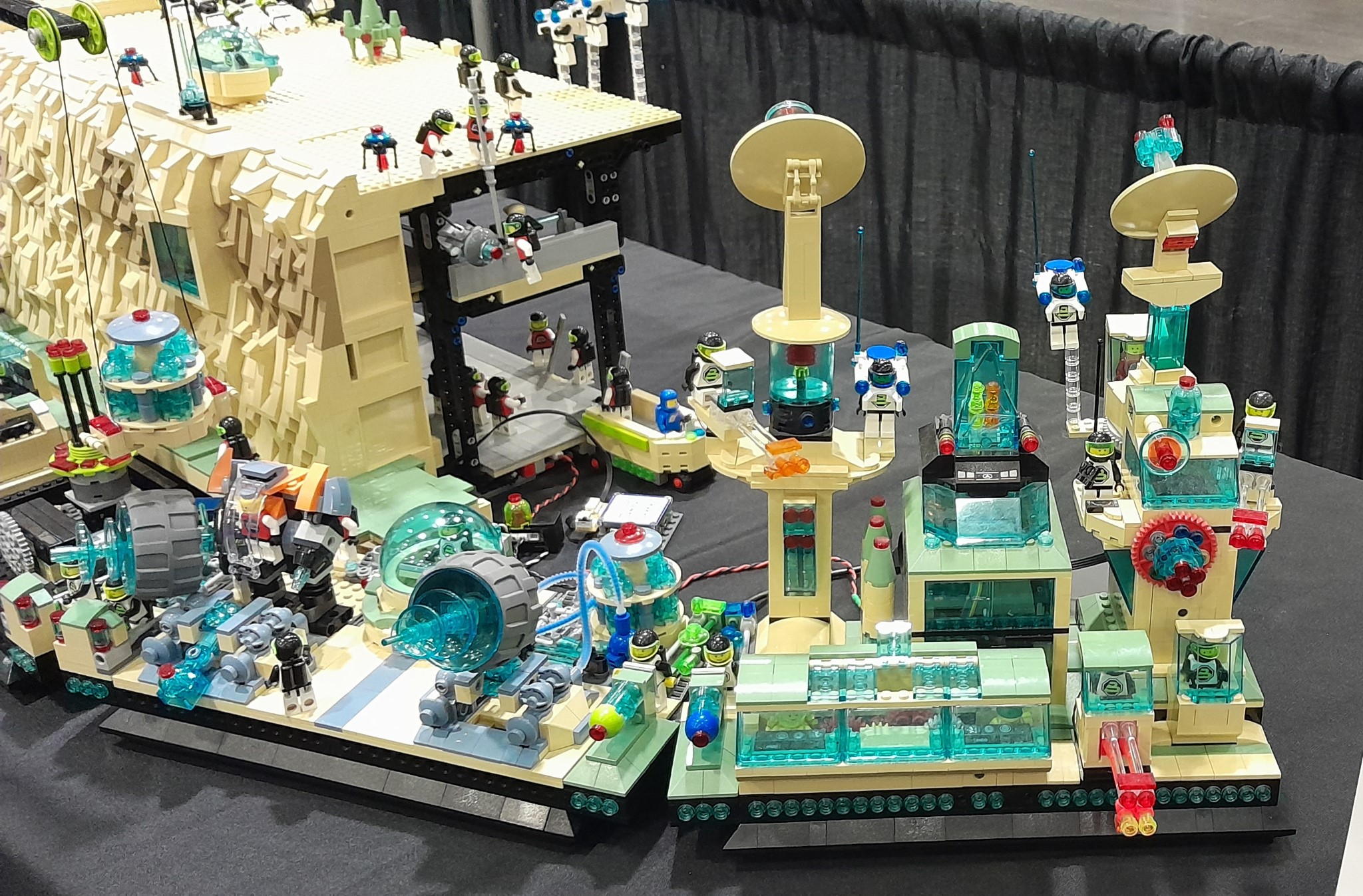
Below are some pictures of the detail in Maintenance Control and the Cyber Cafe.


At MyMakerTools we provide what powers your Maker projects and the Maker tools to be creative. This includes USB Power supplies to power your creations, the Maker Surprise line of Bricks & controllers, HO train goodies to make the layout stand out and soft wear to make your life just a little more comfortable.
Below are some pictures of the detail in Maintenance Control and the Cyber Cafe.

I have discussed wring in several blog posts, here, here, here, here, here and here, among many others.
But what I intend for this post is compilation of the bricks that are used and how basic LED wiring can use these bricks.
First the bricks.


These are the basic Bricks that I use. The wiring shown in the very first picture is 30 gauge wire, either twisted by hand or purchased in the black two conductor ribbon cable. There is smaller wire (higher gauge number) available. However better tools are needed to use these smaller wires as I explained on my website. Just scroll down to wire sources.


These two pictures show how the 1 x 2 Brick with channel can be used. By placing 1 x n Bricks on either side it will provide some support. This method only allows for half of the channel to be exposed, but that is sufficient for the 30 gauge wire used.

This shows the wire running through the channel. Another 1 x 2 Brick with channel is added to help secure the one underneath.

This is the same idea, but using the 2 x 2 Brick with channels. With this brick you can run up to 4 wires up a column if needed. The axle hole in the middle can also be used.
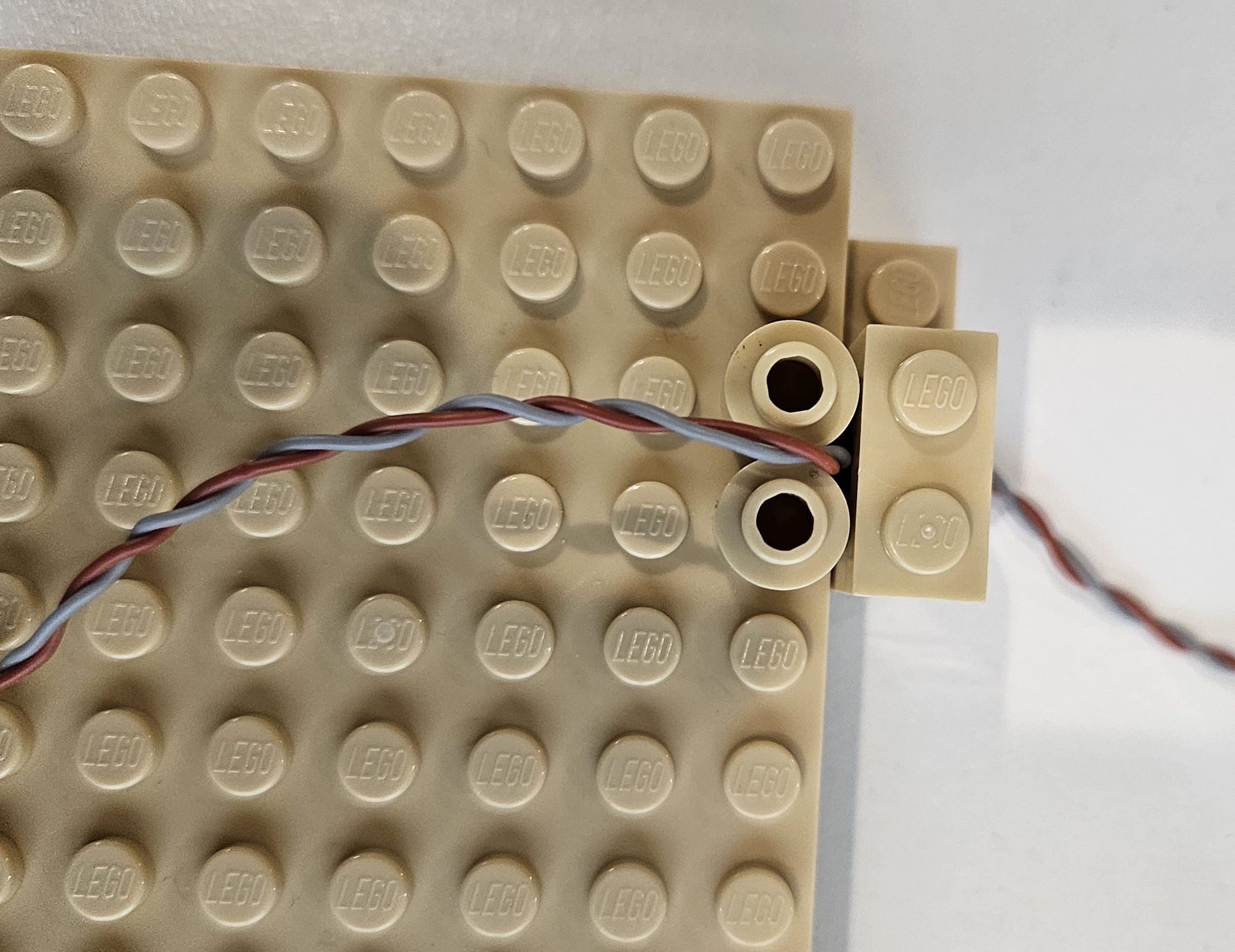
Here I use to 1 x 1 round bricks to create a channel. You can also use 1 x 1 round plates to create the same channel.


These two pictures show how to run wire between two 1 x 1 round plates. The easiest way is what is shown. Place two round plates, then the wire followed by two more round plates. You can do it with just one layer of round plates, wire placement is just more tedious.

This shows a 2 x 6 plate covering the wire in order to hide it.


Finally this is a way to hide a wire run using 2 x 2 curved slope. Obviously a 1 x 2 curved slope will also work. I have used this technique to hide long wire runs. This implementation uses a 1 x 4 plate topped with a 1 x 4 tile. That stack could have been another 2 x 2 curved slope also.
These are just some of the possible ways to run wire inside a MOC. I am sure there are other bricks that can be used also.

The PC interfaces are now going to be consistent as are the Android interfaces. The device API will also be consistent. If the feature is not available on a particular device, a special message will be returned to indicate non-availability.


These are the updated interfaces. You can see the difference in the Light Buddy 2 interface at the top of the page and this one here. Brick Controller ONE did not have PWM control of the LEDs or the Motors, so that functionality is not shown. All the other brick and light controllers have some form of PWM.
More on these updates later.


Finally I have been trying to get the first Light Controller up and running again. When I did it the first time was right at the start of COVID. Then all the parts disappeared. Now that most are back, I am updating the design.


In the last post, I discussed the assembly problems with the floating platform. Since the potential to break wires was very high, I needed a new solution.. Thus I spent the last few days working this out. The floating platform is the first place where I expanded the use of the old 9V 2 x 2 connectors as described in this post with implementation ideas in this post. I took this to next level and used these ideas to eliminate the wires between the platforms, thus it is truly plug and play.

This is the structure that I built to connect to base plates in the floating platform. The orginal version had different ends, not sure why I did that, but it complicated the assembly. It had to go on one way, but it was not obvious which way that was. This is the first change I made, this still goes on way, but that is for electrical reasons.

First I placed a distribution PCB in the base and connected one of the 9V connectors. This is where power will be inserted to the floating platform. It will also serve as distribution point, if needed.


This is what the final assembly looks like from both sides.

I built three of them. Two have power distribution and one does not. The one with out power distribution still has a connector in it. There are no wires. It is used to connect the power between the connecting base plates.


The wire that ran between base plates is now replaced by three 9V connectors. Two of them are on the base plate and connect to the distribution PCB on the floating platform. This is shown in the two pictures above.

To ensure that the 9V connector stays in place and to provide a guide, a 4 x 4 plate covers half of the 9V connector.

While this goes together very nicely now, there is still one problem .

This connector is in the support structure. In the picture of the support structure above, the studs on the left are one polarity and the studs on right are the opposite polarity. That means that the platforms that connect to the support structure have to be mirror images of each other, electrically. To solve this problem the connector and cable on the mirror image platform have to be reverse wired.
Now this can cause a large problem, especially with Brick Controllers that have minimal reverse power connection protection, since all of their power connectors are keyed. So in the picture above you can see there are red tiles and plates. These are there to indicate which base plate side connects to which side of the support structure. Finally I will install an LED on the base plate that has the Maintenance shed. The Shed can only be installed when this LED is on, that will indicate that wiring polarity is correct.
Finally while doing all of this, I also finished the floating platform.

I added the final landing base plate, the one on the far right. I also added a small work area at the grey octagon. I was originally going to add a 16 x 16 plate, but this angular implementation adds more character. This new work area will have the fueling station, since it is accessible to all three landing areas. More on this later.

Well I thought I had solved the assembly and made it much easier. That turned out not to be true.
Over the weekend I was at the BayLUG meeting. I had taken this to the meeting to test the setup process. It had been about 4 weeks since I had set this portion up on the build table. Thus I had completely forgot how this goes together. But it needs to be obvious. There has to be guides that ensure it can only together one way.
Obviously this was not the case, as I struggled for 15 minutes or more trying to align the three platforms. Plus the cable that runs between the base plates is just too short.
So it is back to the build table and another attempt to simplify this assembly. My limitation on the display is now the time it takes to setup and tear down. At 3.5 hours of setup and 2.5 hours of tear down, I am pushing the limits of what is allowable. I cannot add much more because there will not be time for setup and tear down. I would have to radically change the way the display is assembled.
This will be the last post in this series and is about the wiring is run on the cliff side. I sort of forgot to mention this in an earlier post.

Let us break down the above picture a little more.


After exiting the technic 1 x 2 brick, it is held in place with four 1 x 1 round plates. There is sufficient gap between the base of the plates for the wire to placed and held securely.


Here I used the 1 x 1 round plates to create a small channel for the wire to be placed in.

This shows a different view where you see the wire placement. Not shown is another row of 1 x 1 plates up against the panel to allow the wire to safely get into the cavity of the 1 x 6 x 5 panel.

Once the cliff is built around it, we get to the top. The wire needs to run in along the ceiling of the second floor cliff. In the above photo you can see the wire passing through the 1 x 2 technic brick.


Here is an expanded photo, thought the shadows still make it hare to see the wire.
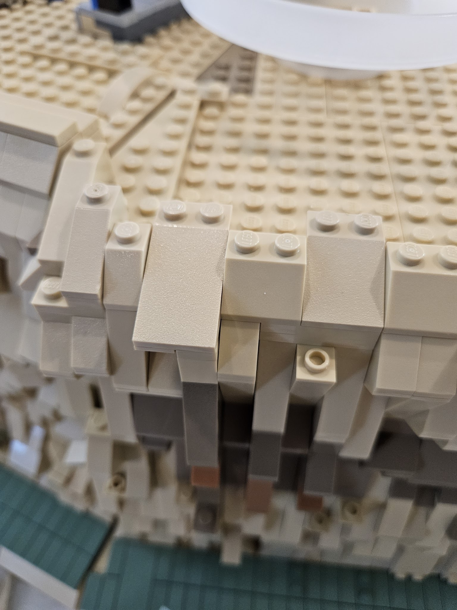
Finally I use a 2 x 4 slope to cover the whole and secure the stacked slopes.
This is just one technique for hiding wires.