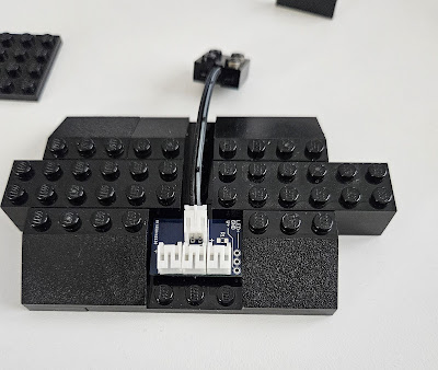
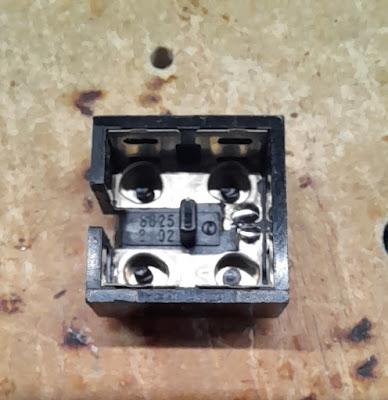
In the last post, I discussed the assembly problems with the floating platform. Since the potential to break wires was very high, I needed a new solution.. Thus I spent the last few days working this out. The floating platform is the first place where I expanded the use of the old 9V 2 x 2 connectors as described in this post with implementation ideas in this post. I took this to next level and used these ideas to eliminate the wires between the platforms, thus it is truly plug and play.
This is the structure that I built to connect to base plates in the floating platform. The orginal version had different ends, not sure why I did that, but it complicated the assembly. It had to go on one way, but it was not obvious which way that was. This is the first change I made, this still goes on way, but that is for electrical reasons.
First I placed a distribution PCB in the base and connected one of the 9V connectors. This is where power will be inserted to the floating platform. It will also serve as distribution point, if needed.
This is what the final assembly looks like from both sides.
I built three of them. Two have power distribution and one does not. The one with out power distribution still has a connector in it. There are no wires. It is used to connect the power between the connecting base plates.
The wire that ran between base plates is now replaced by three 9V connectors. Two of them are on the base plate and connect to the distribution PCB on the floating platform. This is shown in the two pictures above.
To ensure that the 9V connector stays in place and to provide a guide, a 4 x 4 plate covers half of the 9V connector.
While this goes together very nicely now, there is still one problem .
This connector is in the support structure. In the picture of the support structure above, the studs on the left are one polarity and the studs on right are the opposite polarity. That means that the platforms that connect to the support structure have to be mirror images of each other, electrically. To solve this problem the connector and cable on the mirror image platform have to be reverse wired.
Now this can cause a large problem, especially with Brick Controllers that have minimal reverse power connection protection, since all of their power connectors are keyed. So in the picture above you can see there are red tiles and plates. These are there to indicate which base plate side connects to which side of the support structure. Finally I will install an LED on the base plate that has the Maintenance shed. The Shed can only be installed when this LED is on, that will indicate that wiring polarity is correct.
Finally while doing all of this, I also finished the floating platform.
I added the final landing base plate, the one on the far right. I also added a small work area at the grey octagon. I was originally going to add a 16 x 16 plate, but this angular implementation adds more character. This new work area will have the fueling station, since it is accessible to all three landing areas. More on this later.


No comments:
Post a Comment