
At MyMakerTools we provide what powers your Maker projects and the Maker tools to be creative. This includes USB Power supplies to power your creations, the Maker Surprise line of Bricks & controllers, HO train goodies to make the layout stand out and soft wear to make your life just a little more comfortable.
Sunday, June 17, 2018
Tulsa Maker Faire
We will be at the Tulsa Mini Maker Faire on Saturday August 25. Hope to see all of you in the Great state of Oklahoma. Not sure what we will be showing, but keep watching this blog or follow us on twitter to see what is happening, @MyMakerTools and #MakerPower.
Friday, June 8, 2018
Center Platform (Update)
Trying some different ideas on how to fill this space. Have been looking at dual cannon design from the Death Star set. (For us old Navy types, looks a lot like the 5""-38 twin mounts on the original Iowa class battleship configuration). Here are two views of the twin mount.on the center platform.


In this context the proportional size just does not look correct. There is still work to do here.


In this context the proportional size just does not look correct. There is still work to do here.
Thursday, June 7, 2018
Vertical Generator Build (Part 2)
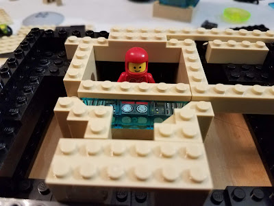
Made more progress on the build. There are two containment charging stations on either side, both located below the surface of the platform. Each one has a space for the canister to be lowered into the charging area. Inside of this will be several LEDs that will randomly flash when charging the canister. Then there is a control room behind glass that a minifig will control.

Here is the control room.

and with the minifig in place.
a different view
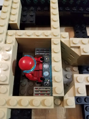
some what better view of the control panel.


wide angle views from front and back

Here is what the generator looks like in dry fit.
Next job is to figure out the LED arrangement. My first idea kind of melted on me, so I am regrouping on what to do. More next time.

Here is the control room.

and with the minifig in place.

a different view

some what better view of the control panel.


wide angle views from front and back

Here is what the generator looks like in dry fit.
Next job is to figure out the LED arrangement. My first idea kind of melted on me, so I am regrouping on what to do. More next time.
Wednesday, June 6, 2018
Vertical Generator Build (Part 1)
While I am waiting for parts to come in, I have started on motorizing the vertical generator. Here is mock up.

Here is the base broken down for working on the underlying infrastructure.

The front is at the top of the picture. Here is another view.

The two cavities on either side will contain a work area with minifig(s) and LEDs to show a charging containment field. The attention is lots of detail in each one. The motor in the back will drive the generator. I compressed the motor arrangement as much as I could, because their might be another motor in the front section.
Center Platform
While most of the center platform is done, there still remains a fairly large space on either side of the center steps. My intention is that there will be no motors on this platform, but lots of lights.
Here was my first attempt at using that space.

The idea was to have a large formation of troops there. This would have been 22 Minifigs. I have that many Blacktron IIs, but that would have put a crimp on using them elsewhere. My independent artistic consultant (my youngest son) did not like the idea at all. So it is back to the creative well.
Friday, June 1, 2018
Horizontal Generator Build (Part 4)
Now I can work on the structure and detailing.

Here the generator has been attached as shown in the earlier post. There were some minor changes in the detailing.

Here the large control panels have been added.

A closer view of the large control panels.

Here the glass structure has been added along with the Minifigs.

Finally one cannon on the left and a partial spinning cylinder on the right. Don';t have all the parts to go any further. Looking at different colors for the cannon. There will be hoses coming off of the large generator going into the platform. This will follow the lime and blue color scheme used elsewhere.
There is still more detailing to do, but this has finally taken shape. Here is a short video of it running. Still needs LEDs to properly light things up.
Horizontal Generator Build (Part 3)
I made progress on the undrlying gearing to control this platform. It was more difficult than I thought it was going to be. Here is where I started from.


Here is where I ended up. The added section controls the rotation of the two large cannons. (The picture was a little fuzzy unfortunately, late at night and I was not very steady)

Another view.

I am probably going to leave this corner area open to show the gearing. Also I suspect that the rubber band will have to be replaced every so often and this will allow for easy access.
Next is the structure on top.
Subscribe to:
Posts (Atom)