
Here are three scope shots that show the pulse width for the 1ms, 10ms and 25ms timer settings. I use the timers in both a blocking function and as an interrupt driven timer. The PIC18F25K50 has two 16 bit timers that I use for this. The two 8 bit timers will be used for the PWM engines.
Here are the scope pictures.
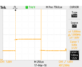 |
| 1 ms |
 |
| 10 ms |
 |
| 25 ms |
1ms => 1.005555ms or 0.5555% error
10ms => 10.01645ms or 0,1645% error
25ms => 25.05286ms or 0,21145% error
This is good enough for timing the light s on a MOC.
Next is to install the LP5569 LED controllers and get the I2C bus working. Never used these before so it should be interesting. Plus these are very small parts, so installing is going to be fun.
No comments:
Post a Comment