
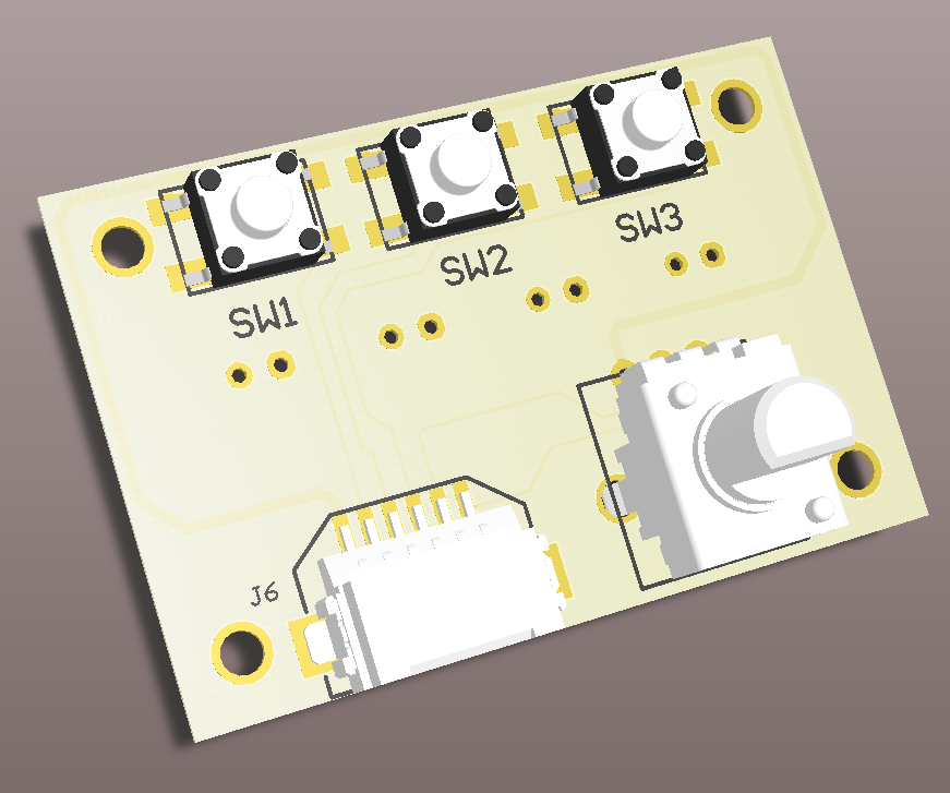
To save costs, this board will be dual function. One side will do the input function, as shown above. The other side will be the output connector for the two PIC PWM controllers and the two ON/OFF LED controllers, see below. The assembly will be one or the other and not both, at least not right now.

The above are 3D models of what these look like. My only issue with the design is the connection of the outputs. Right now these are standard 0.1" spacing connectors. You can either solder directly to the PCB or put in 2 pin connectors and connect to them. Could put in the JST type connectors used by the LiPO batteries that are popular on the Maker Sites. but building mating cable connectors is difficult. In the end, it seems easiest to just wrap wires around post.
No comments:
Post a Comment