Started building the horizontal generator as a standalone model so that I can test the functionality and figure out how to light it. Here are the two sides before assembly. There are three brackets (P/N 44278) that will hold the two sides together. Also the gear box (P/N 6585) is sandwich in between.
There needs to be reinforcement to ensure that gear box does not move under load and that the brackets stay in place. The top of the gear box is captured by multiple pieces to keep it locked down. The brackets are kept in place by 2x2 plates that themselves are captured.
It is important that all pieces be securely and completely pressed into place. When the two sides come together the fit is exact. If the pieces are not pressed into place, there will be undo stress on the 2x2 plates that connect the two assemblies together.
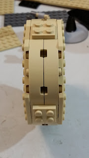
The two assemblies are held together by three 2x2 plates, which are then covered by six curved slopes. Once this step is complete, changing out the axles is easy since the gears are captured. Just make sure you only change out one axle at a time.
For the spinning portion, I am using a tan 8x8 dish to hide most of the studs of the 10x10 octagon plate and to give the model some smooth lines. Next are back to back 6x6 dishes. These are temporary colors for now ( this is just what I had in the pile of parts). The longest axle will not reach the end of the cone, but it should have sufficent support to still spin.
The base is secured using Techinic beams and pins as shown here. Curved slopes and decorated tiles are used to finish out the detailing. This may change in the final design, but for now it smooths out the blockiness. Because this base is not longer an integral number of studs, the long pins (P/N 6558 or 32556) are used to be able to adjust the position of the drive axle that will be hidden underneath the generator.
Next step is to build a temporary platform to power the device. That is where we will see if this actually works.


No comments:
Post a Comment