Tuesday, December 12, 2023

Brick Palooza - Part 2


Here is a link to the Brick Palooza Facebook page.

And a link to a video of our display.

And here are some of the more interesting MOCs at the show.

I was interested in the detailing with the plants in this one.

This and the three pictures that follow show D-Day on Omaha beach.  It was a very impressive display.


This one was very colorful and detailed.


Interesting use of sand green color.


A collection of castle sets.

This was a depiction of the Mad Max world.

I really liked the water simulation.


Pictures of some kitchen ideas for when I detail out the kitchen area of the cafeteria.

A recreation of the bar from Cheers.  I may have to put in a bar when I do the living quarters. 

Yoda and Christmas.

Then there were a group of COS Players there as we see in these pictures.


The Omaha Beach MOC was best in show.


We were the winners in the Space Category.


Monday, December 11, 2023

Brick Palooza - Part 1

And Brick Palooza begins.

First load of boxes.


Setup begins.

Setup was different this time.  We were at the end of the large enclosed rectangle.  Thus we we had an 8 foot table and the 30 inches of the two tables that came up the sides.  Total linear distance of 13 feet.  The calculated length was just under 12 feet.

The plan was to center the display on the end.  But this time instead of having one table break, there were two.  And they were definitely not level. I started building from the perceived center, which is the main entrance and tower.

The modules are assembled as a slice.  The main module in the front, the cliff and then plateau/hanger section.  Then this assembly is slid towards the main entrance.  There are a few technic pins that align and hold the parts in place.  Assembling the slice is fairly easy and goes together quite quickly.  It is just remembering to attach the power connections for everything that has power.

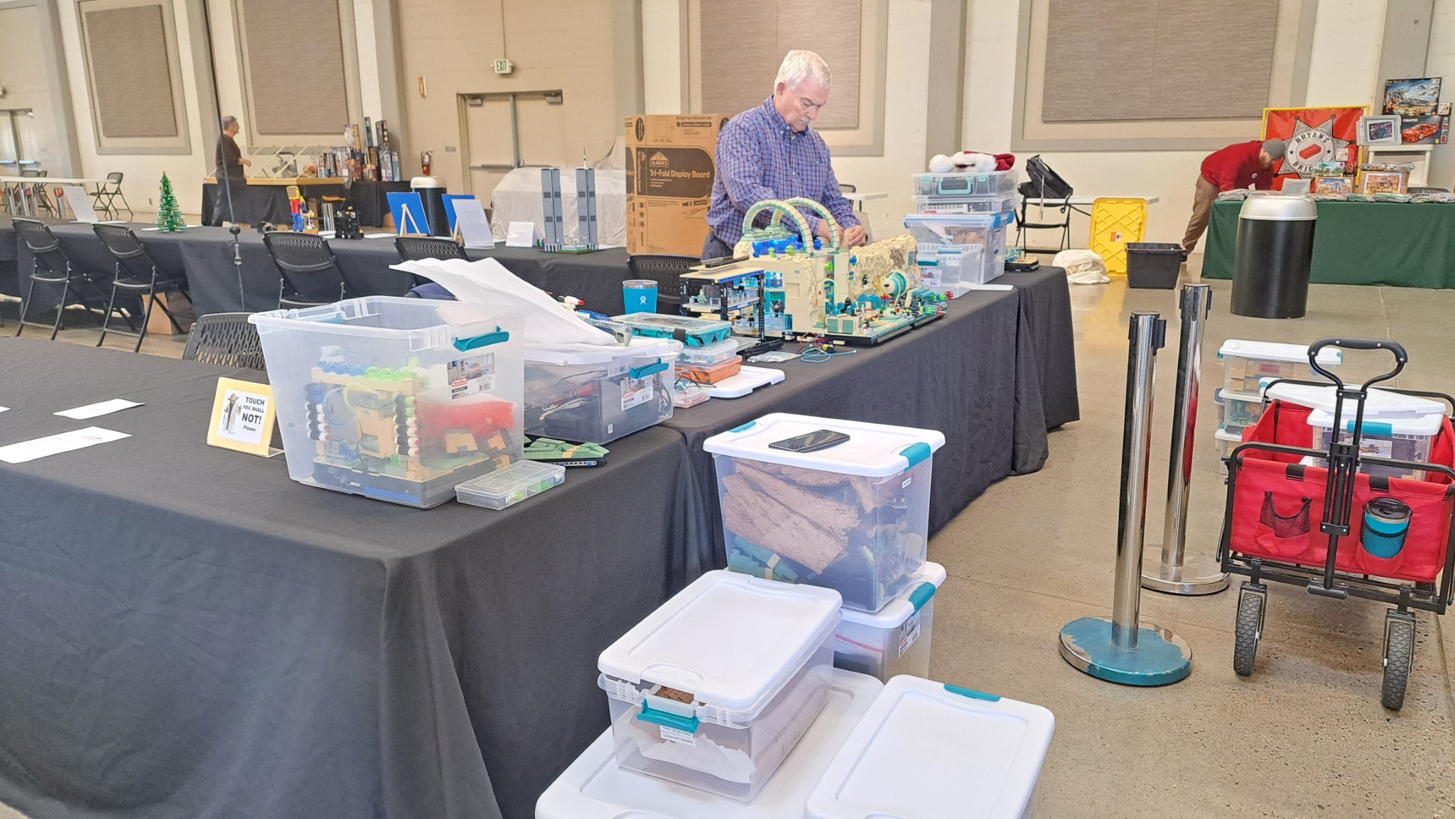
The hangers have to be assembled, since the assembled version is too big to fit into the box. Over the last few shows I have reduced the time needed through reducing the technic pins needed and how the cantilever section is held up.  There is still some work to do on the second level platform that mates into the cliff.  When the cliffs are redone, this platform will partially move to the cliff and this setup/assembly will be eliminated.

This is trying to get the technic pins to line up.  Even though I have reduced the pin count to a bare minimum, trying to get  4 to 5 pins to line up is difficult and takes upwards of 5 minutes to get them to engage.  This is a huge opportunity for improvement.


The left side is done.  It is now apparent that the physical center is not on the main entrance.  The landing platform has skewed the center to the right.  But this worked out.  The last hanger is on the end of the 8 foot table.  The platform connector spans of the table gap.  The next platform is then on the end table.  Since the platform connector does not rest on the table top, it floats above the gap.  This is the best of all worlds.  In the future, we will be setting up so platform connector goes across any table gaps.


As the assembly continued, the large roll  up door used for access also let the setting sun in.  This made it challenging connecting the modules on the let side.


This is beginnings of the Terra forming on the top.  It will be a combination of wedge plates and tile.  There will be minimum vegetation since this an arid planet.  But the there will be these different colored crystals.  This will be a new part of the back story.  Part of the reason this Outpost is here is to mine these crystals.  The different colors represent the different stages of development of the crystals.  They reach there full energy potential when they are neon green and glow.  I intend to place UV LEDs inside a large collection of neon green crystals to make them glow.

And the previous event's flags and Minifigures go up, indicating the build is complete.


And we are done.


Saturday, December 9, 2023

New Detailing Addtions

Here is the beginnings of the detailing of the new cliffs and attached platform structures.  In this photograph there are four areas..

Upper left - recreation room and shower area behind it
Lower Left - dining area, kitchen behind that but still needs to be built
Upper Right - gym
Lower Right - mission planning

This will be a recreation room.  Needs more furniture, a bookcase and maybe a pool table or something like that.  The tub still needs a faucet and the walls will need something.  The changing area on the right will also need wall treatments as well as the tiled floor.


The dining area is mostly done.  More stools at the bar area and changing the bar trim to dark red with some studs for food and drink.


The gym is also mostly done.  Need to add a very large screen to the far back wall.  This will have some large landscape on it to remind the inhabitants of what a lush green planet looks like compared to the outpost they are on.


The mission planning area only has the one planning table installed.  This still needs some deep thought.


Friday, December 8, 2023

Improved Power Distribution

 The hangers/covered corners contain the main power distribution feed. When there were only four of these, on either side of the main entrance, this was not that important.  But now that there are going to be at least four on each side, this needs some attention.  Each hanger had a standard two pin connector on each side and then a three connector block in the back.  The idea was that two hangers would connect together and form a power distribution path.  But that was using 30 gauge wire, which is not sufficient for the amount of current that will flow with four hangers/covered areas, four cliffs, four modules and an unknown number of powered platform connectors.  Thus I am changing the wiring in all these hangers/covered corners to 20 gauge.  I am also considering placing an electrolytic capacitor (100uF) in each one to help buffer the current when the motors turn on.  This backbone will run from the connection side, (right side on left modules and left side on right modules) to the other side of the platform as well as to the back. This shown in the picture above.


On some platforms, the opposite side is just a wire with connector.  When the two platforms slide together, the wire has to retract into the platform, otherwise it will prevent the two platforms from mating properly.

This shows the wire with connector.  I also had to put tiles in, since the wire was hanging up on the studs when the two platforms were pushed together and the wire was retracting back in.


Thursday, December 7, 2023

More LED Wiring

The new additions all needed LED lighting.  I used the same techniques as before.  You can see the 2 x 2 modified plate with pin holes everywhere acting as a form of conduit.  What has changed is wire.  Instead of two 30 gauge wires twisted together, I am now using 2 conductor 30 gauge ribbon cable.  It is from the same company and has a silicone jacket so I don't have to worry about shrinkage when soldering.  Here is the Amazon link to the wire.  The twisted wire will actually go into smaller places than the ribbon cable.  This is because the twisted wire is more round and the ribbon cable is going to be rectangular.  Now with that said, that issue will not com up too many times.  

Here you can see I am going through the holes in the Technic bricks. This also serves to hold the wire up against the ceiling so it cannot be seen.

Another example of how to use the 2 x 2 modified plates.

What is interesting here is that the wire is small enough to go through the pins that are holding the Technic bricks together.  Thus when passing through Technic bricks there are few restrictions as to which holes can be used.


These just show placement of the LEDs and the 2 x 2 modified plates.


Wednesday, December 6, 2023

Building a Corner Section


This is a partial corner section behind the Space Port.  There are three pieces in this.  From right to left, the Space Port it self, the cliff section and then the covered area (which is the same as the hanger areas on the straight sections).  The cliff has two floors built into it.  The bottom floor includes a tunnel to the Space Port and staging area for missions.  The Top floor is an extension of the gym.  The covered area also has two floors.  The bottom floor is a mission planning area and an extension of the staging area in the cliff.  The top floor is a continuation of the gym. Since this is the end of the display, I also added a window on the end of the covered area.

The major issue with this build is the lack of post or support column for the top floor and the roof in one corner.  This is shown above as the 45 degree cutoff has no post.

This shows a closeup of the support structure underneath the top floor.  This is a labyrinth of Technic bricks and pins.  There are multiple right angle supports as well as box supports.  I should have taken the time to put this in Studio.  That would have allowed for a cleaner design.  This may still happen.  The same technique was used on the roof.

This shows the bottom floor mating with the next module.  Using 3 x 3, 4 x4 and 6 x 6 wedge pieces, I created a 45 degree edge on the bottom floor, top floor and roof.

It would seem that extending out the Technic bricks would be the simple solution.  But you have to careful not to impact the next module over.  Square brick ends and 45 degree angles do not mate well.


These show the finished base structure with opening on the top floor and the staircase going up.