I have spent the last few days working on the I2C driver that I need for the LP5569 LED driver. This is one component that received a major change from Harmony v2 to v3. Most of API had their names changed and few things were added/deleted.
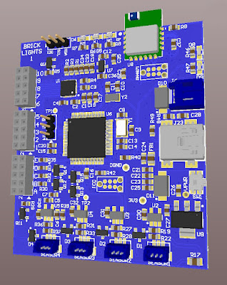
First for Brick Lights 1, I changed the board to eliminate the individual connectors for each LED that used the very small two pin connectors, the working proto is shown here.
I used the 2mm header (2 x 5) that I used in the Brick Buddy 3. I also changed the BT module to the smaller RN4871. This also allowed for the board dimensions to shrink 8mm. This is the new layout.
The first picture is the device that I am using for the development, while I wait for the new PCBs to arrive. I should mention that under Harmony v2, most if not all of this proto was working. So I know that the design was good.
After generating all the I2C components in Harmony 3, I started the process of implementing the application layer code. While Harmony generates the drivers and middleware, you still have to implement the application layer. That took over a day to get to the point that it would compile and at least appeared to communicate with the I2C drivers. This I2C implementation is interrupt driven which for the most part makes it non-blocking.
No matter what I tried, the driver would report an I2C error when transmitting a simple command. Trying to follow the execution path down into the driver was not yielding any useful info. After two frustrating days, I decided to try a different approach. I have a PIC32MX470 Curiosity board and there was an I2C EEPROM example. Also the Curiosity board allowed me to connect my Digilent Analog Discovery device very easily. This device has an I2C decoder built in, thus I can see the commands and the protocol to determine if it is working correctly. While the EEPROM was responding correctly, the firmware still not see it. Stupidity number ONE. The comments for this example were very specific to make sure the CLICK sockets were connected with ZERO ohm resistors. Well they were not. The 1K resistors were just enough to screw up the PIC32 read. Once I got the example code running, I modified it to more resemble the code flow I was using. Now that I know this was working I could go back to the proto with some confidence.
Well still not working. Attached the wires for SDA and SCL so I could watch the I2C protocol exchange on the Digilent device. First thing I see is the device address is wrong. With a 7 bit I2C address in Harmony v2 the user was required to shift 1 bit left, but in v3 the driver does that. Thus the device address had been all wrong. Stupidity number TWO. Once this was changed the I2C exchange started to work, but would not complete.
Side step, when I first started using TI LED Drivers, I was using the LP5569. Then COVID and they disappeared. But I could get LP55231, and earlier version that was 90% firmware compatible, though the outputs were inverted. THE LP55xx driver that I wrote would mostly do both, though I had not completely tested it on the LP55231 since the LP5569 became available again. The new layout will use the LP5569. This proto was the only device that actually had the LP55231.
Looking at the I2C trace, I could see that the final ACK was not coming in. After hours of research, I found that the LP55231 required a software Chip enable for some commands to work. How this worked before I am not sure, but I decided to just move on. I modified the startup loo. Stupidity number THREE.
Now the entire initialization of the LP55231 completes and the status read back shows all the registers are where they should be, just not at reset. I still need to check if the LEDs actually light up, but for now I have high hopes it will work.
On to the BT module.


