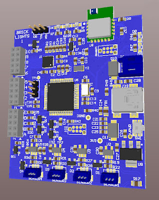
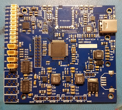
For multiple reasons I am resurrecting what was my second Brick Controller. This was started in 2019. But between our moving from the Bay Area and Covid, it never got beyond the original PCB. That PCB had issues in the design. Here is a link to one post, but there is a whole series of posts in 2019.
The firmware was developed with Harmony version 2.06. This version is no longer supported. The Light Buddy 1 had a similar processor, a PIC32MX270 vs a PIC32MX470 in the Brick Controller. The Light Buddy 1 firmware was developed using Harmony version 3.0.
Here is my setup
- Win 11
- XC32 4.40 and 2.40
- MPLAB 6.25 uses PICKit5 and custom PCB
- MPLAB 6.10 uses PKOB3 on Curiosity PCB
- Debug using only hardware breakpoints
I took the original PCB and used the Light Buddy 1 firmware as a basis to start the upgrade in Harmony 3. The original design with multiple peripherals did not work. I stripped it down to nothing except CORE, UART2, System Console and DEBUG. As long as app.c had nothing in it, the program would generally run. If I added a SYS_CONSOLE_PRINT command or even toggle a GPIO port, then it would throw an exception. Generally 0x07 or 0x0A. For a while it was at a consistent address, but when trying to look at disassembly, the address would move.
I moved the code to the Curiosity board with exactly the same results. Please note the Curiosity board has a built in debugger. Also note this is a generation 3 debugger so I was limited to using MPLAB version 6.10. But this also means the debugger is probably not driving the problem.
But if i just program the custom PCB with the firmware it works as expected. this includes the toggling of the onboard LEDs and using UART2 for a console message output.
I tried
- Slowing down the clock speed
- No prefetch
- Longer FLASH wait states
- No interrupts
- deleted the linker file and used the default one
and probably a few other things I have forgotten about, since I had been at it for multiple days.
I posted in the Microchip Forum and received and interesting reply. They suggested I use the following menu item in MPLAB.And the debugger starting working, kind of. In MPLAB 6.25, the debugging process was slow and sluggish. If I closed out the project and then loaded the project into MPLAB 6.10, it worked more as expected. Occasionally the exceptions would come back and I would have use the above menu item
My conclusion is that in MPLAB 6.25 the debugging process leaves some errant code in the processor. While starting the debugging process erases memory, evidently what gets erased by starting a debug session and what this menu item does, are different.
On to testing everything else. and working on the schematic design of the upgraded PCB.


