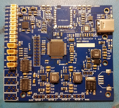
Brick Controller 2
Brick Controller 3
Light Buddy 1
Light Buddy 2
I am up to four devices now that have some form of common LED lighting. Two of which have motor controllers, the basic PWM interface. As I keep developing new LED lighting effects, going back to each one of these devices and making the changes is getting too time consuming. Not to mention that I am not getting consistent effects.
Earlier I started on a quest to make a common library of firmware that can be updated and then automatically apply across all the device platforms. After a few days of work and frustration 😎, I have achieved success. Though there is still some testing to be done, but the basics work. Here is a short description of how I got there.
The two LED controllers I am using right now are LP5569 and LP55231. I use these because they are mostly firmware compatible with each other. Though one is a low side driver and the other is a high side driver. When I am not using these LED controllers, I use the built in PWM controllers in the PIC processors. Finally when the LED is very basic, either off or on, then the control is the generic IO control of the PIC processor. Regardless of the driving source, my hardware designs abstract the source away and present a consistent hardware interface of a low side driver.
Both the LP5569 and LP5231 have I2C interfaces. These were the only devices in any of these designs that had an I2C interface, thus the I2C driver was intertwined in the LP55xx code. The first step was to extract the I2C driver code and make it a standalone module. While this was not difficult, it take some time to "unwind" all the code. Now I can add other I2C devices, without having to include I2C driver code.
Next was to unwrap the the LED effect (STYLE + FEATURE) from the driving source (LP55xx or PIC). This meant creating two different modules, one for the LP55xx and one for generating the LED effect. As has been described in previous posts, the LED effects reduces to a PWM value in either the controller or the PIC processor. Thus the module I call PWMCtrl, generates this single PWM value for any 100ms time slice. Then if a LP55xx is the destination, the value is passed to that module for writing into the LP55xx IC. (Actually because of the way these ICs are set up, all nine channels are updated in a single transfer. Thus I wait until all the LP55xx LED channels have their PWM values updated before transferring data.) If the destination is the PIC processor, then it is a simple register update.
The final change was actually splitting the PWMCtrl module into a common section and a local section. The local section contains all of the device initialization, the cooperative task function and any hardware dependence. The common section is mostly the LED effects generator. This code computes the PWM value needed. Thus I now have one place where all effects are calculated, which provides consistent looking effects. I have not looked very carefully at this split. There probably is a way to combine these through some MACRO definitions. But that will be for later.....


No comments:
Post a Comment