

This is very embarrassing. The new PCB for the Solar Shed has multiple problems and they are just dumb mistakes. I can't believe I did not catch these. So here is the revelation of what happened.
Digital vs Analog Inputs
The PIC18F4525 is an older PIC. During the design process, there was a nagging issue in the back of my mind on how the ADC actually connected to the I/O pins. Early on in my designing with PIC processors (PIC16F876 and PIC16F877), I was burned by an issue with the ADC. I did a cursory look at the PIC18F4525 data sheet but could not find anything that was out of the ordinary. When I was changing the firmware to accommodate the PIC18F4525, I finally found it, but this was after the PCB arrived in hand.
This is an excerpt from the PIC18F4525 data sheet. This is one of the registers that controls the ADC. In particular look at Port Configuration Control Bits. These four bits determine which I/O ports are digital inputs and which are analog inputs. But you don't have complete freedom. This is a cascading implementation. As an example if you need AN5 to be analog, then AN0-AN4 also have to be analog.

Well if you have not surmised already, the three inputs that I used are AN5-AN7. That means the I/O pins AN0-AN4 are also analog inputs. This translates to RA0=RA3 and RA5. I did not use RA5 and RA0-RA3 are used for i/O control of the OLED display. What I should have done was finish the firmware changes for the PIC18F4525. That way I would have run into this before I submitted the PCB design.
SPI Connections
Next issue is even more embarrassing. I did not correctly connect the SPI to the OLED. The PIC18F4525 is before PPS (Peripheral Pin Select) which let you have some flexibility on moving PIC functions to different I/O pins. As you can see from the schematic snippet below, I built the symbol correctly as RC3-RC5 are labeled with the SPI pins. I just did not connect the wires. This is mostly a cut and paste failure. I copied this circuit from a previous design that used a PIC18F47J50 that had PPS. Somehow in the process of checking this, it went right by me.

Solutions:
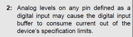
- Software fix: Since I use the ADC every few seconds and the OLED display is strictly user initiated through one of the push buttons, I could change these four bits in ADCON1 to reflect current usage at the time. However there is this warning (shown below) in several places in the data sheet about having analog inputs on a digital input. And even if I pursue the software fix, the SPI issue will have to be a "cut and jump" approach.

- New PCB: So I only paid $5 for five PCBs and $27 to ship it and 3 other PCB designs. Total cost was about $12 for the five PCBs. So I am not into it for a lot of money. This is just a time factor. Redo the design, submit and wait for delivery.
- New Processor: I was trying to use existing parts I had. I have other 44 pin TQFPs on hand. All of them are USB devices and thus have a slightly different pin usage. Mostly the USB pins and internal regulator that needs a capacitor on the pin. Not a good choice. So I started looking at what other PIC18F processors come in a 44 pin TQFP. The parameter tool on the Microchip website was not as good as it used to be. It is pushing newer parts that are not what I am looking for. What I need is a basic 44pin TQFP with PPS. So I went to Digi-Key and used their search tool. What popped up was a PIC18F46K40, which is the next FLASH size down from the PIC18F47K40, the part in the HPC Curiosity board this all started from. The difference is 64K vs 128K FLASH program space. And it was $2.50 in quantity 1.
Where am I, well I am thinking of the PIC18F46K40. This time I am going to do all the software changes first and make sure the current PCB layout will work. If that works out, then I will buy two PIC18F46K40s and go from there. If not, then it may be hacking up the board to make it work. I only need one.
No comments:
Post a Comment