

At MyMakerTools we provide what powers your Maker projects and the Maker tools to be creative. This includes USB Power supplies to power your creations, the Maker Surprise line of Bricks & controllers, HO train goodies to make the layout stand out and soft wear to make your life just a little more comfortable.
Wednesday, May 14, 2025
Tuesday, May 13, 2025
Garbage on the Space Outpost

As past of the effort to detail the space outpost, garbage handling came up. There are two approaches to detailing, fun action related things, ie building walkers, attacking the aliens, etc. Or you can work on the "hum drum" that makes any large complex run, ie, maintenance support, food service, gym, showers, sleeping quarters and garbage handling.


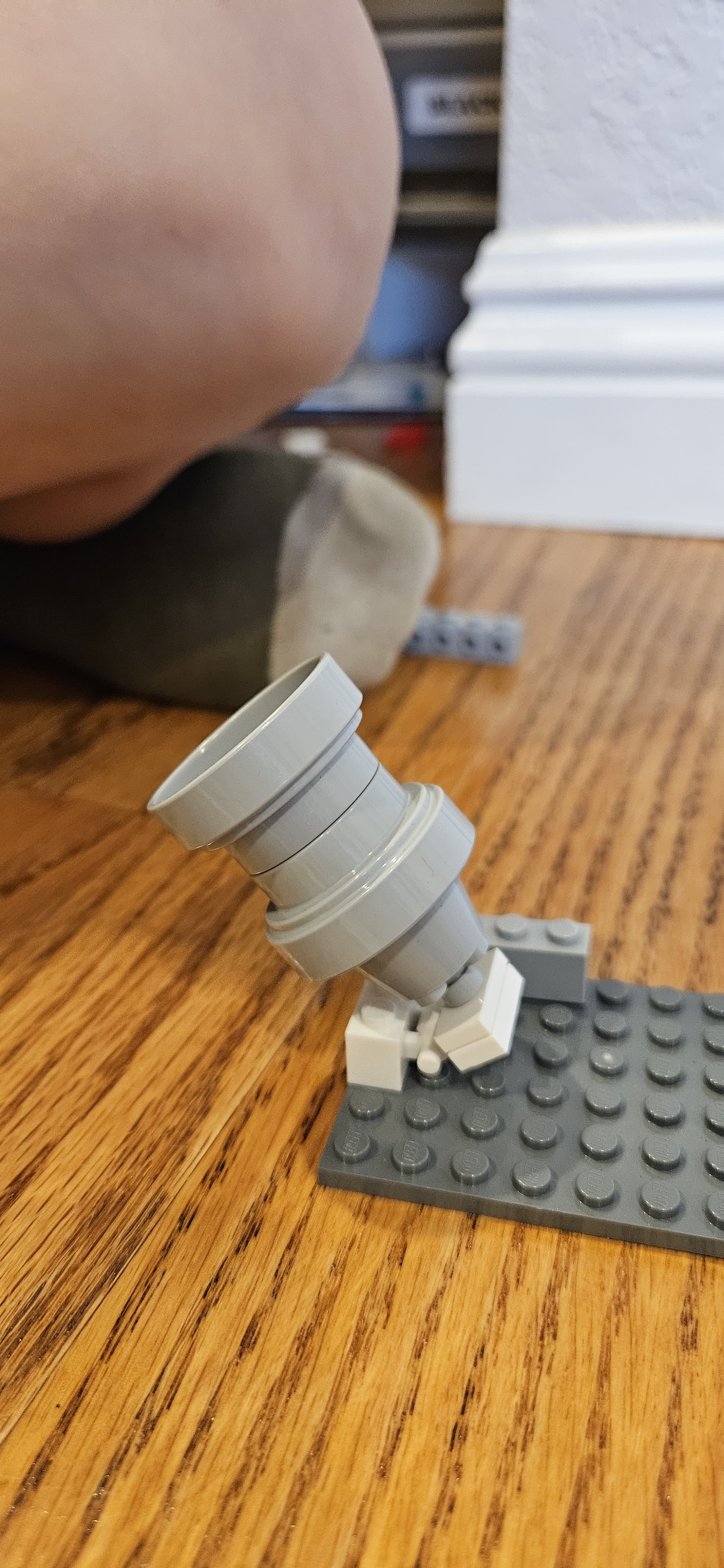
My idea was incinerators and maybe a garbage crusher. These two pictures above show the beginnings as I play with incinerators and the openings. I saw these circular openings elsewhere and decided it was perfect for this. It gives the illusion there are doors in them that will close when needed. The bottom picture shows three different possibilities. I settled for the one on the right as the basis.

Here is the close to final design, without the circular openings. There is an incinerator on either side and the garbage crusher in the middle. There is a control panel for operation.


This is installing the lights. I went with cool white on the incinerators and RGBW Led on the crusher. Except I only connected the RED and BLUE.
Here it is with the LEDs on. You can also see some of the detail that is included is included in the incinerator rooms. After seeing this, I am going to look at putting the small LED controller in to varying the lighting. The garbage crusher also needs work. Unfortunately, there is no place to put a motor, that would be ideal for the crusher.
Monday, May 12, 2025
Loose Ends #7


What follows are some random ideas that came up while building with the grand kids.


I am not sure what these creations will lead to. But one of the overall treatments needs to the so called greebling, and that is probably where this is eventually heading
Thursday, May 8, 2025
Just Harmony

Well after a few weeks of work, I may be there. The software component lefty to implement is the script manager. This is mostly software with a dependency on the Non-Voltaile Memory driver. Since that is working with the config data, what remains is verifying it works on the larger memory needs of the script manager.
The last problem child was the Bluetooth and the RN487x interface. First the UART driver did not work anything like the previous model. As a result the Tx function is blocking, kind of, for now. Not sure how important that is. In the RN487x implementation, I wait around for the CMD prompt before executing the next instruction. I could have the ISR process the flag the main loop when this happens, but this is only important on initialization. For now I am just going to leave it as an inline process that runs to completion.
The Rx function works like before with an ISR that processed the Rx queue from Harmony. I did have to use the Ring Buffer implementation. The normal implementation required that you submit a read request, instead of just using the call back when a byte came in.
There was another problem, but this had to do with Android software I had thought I had solved this problem several years ago, but it came back. It has to do with how many bytes are transmitted when writing a Bluetooth Characteristic. Once transmit 8 (the maximum I set up), then in that session it will always transmit 8. If you send 4 bytes, it will just stuff the other 4 bytes with the last 8 byte transmission. You can read about this issue here.
Time to move on and finish this to the point I can start to assemble the new PCBs. I have a place for at lest on of these 15 channel LED controllers.
Saturday, May 3, 2025
More Harmony, Less KAOS and some Stupidity

I have spent the last few days working on the I2C driver that I need for the LP5569 LED driver. This is one component that received a major change from Harmony v2 to v3. Most of API had their names changed and few things were added/deleted.
First for Brick Lights 1, I changed the board to eliminate the individual connectors for each LED that used the very small two pin connectors, the working proto is shown here.

I used the 2mm header (2 x 5) that I used in the Brick Buddy 3. I also changed the BT module to the smaller RN4871. This also allowed for the board dimensions to shrink 8mm. This is the new layout.

After generating all the I2C components in Harmony 3, I started the process of implementing the application layer code. While Harmony generates the drivers and middleware, you still have to implement the application layer. That took over a day to get to the point that it would compile and at least appeared to communicate with the I2C drivers. This I2C implementation is interrupt driven which for the most part makes it non-blocking.
No matter what I tried, the driver would report an I2C error when transmitting a simple command. Trying to follow the execution path down into the driver was not yielding any useful info. After two frustrating days, I decided to try a different approach. I have a PIC32MX470 Curiosity board and there was an I2C EEPROM example. Also the Curiosity board allowed me to connect my Digilent Analog Discovery device very easily. This device has an I2C decoder built in, thus I can see the commands and the protocol to determine if it is working correctly. While the EEPROM was responding correctly, the firmware still not see it. Stupidity number ONE. The comments for this example were very specific to make sure the CLICK sockets were connected with ZERO ohm resistors. Well they were not. The 1K resistors were just enough to screw up the PIC32 read. Once I got the example code running, I modified it to more resemble the code flow I was using. Now that I know this was working I could go back to the proto with some confidence.
Well still not working. Attached the wires for SDA and SCL so I could watch the I2C protocol exchange on the Digilent device. First thing I see is the device address is wrong. With a 7 bit I2C address in Harmony v2 the user was required to shift 1 bit left, but in v3 the driver does that. Thus the device address had been all wrong. Stupidity number TWO. Once this was changed the I2C exchange started to work, but would not complete.
Side step, when I first started using TI LED Drivers, I was using the LP5569. Then COVID and they disappeared. But I could get LP55231, and earlier version that was 90% firmware compatible, though the outputs were inverted. THE LP55xx driver that I wrote would mostly do both, though I had not completely tested it on the LP55231 since the LP5569 became available again. The new layout will use the LP5569. This proto was the only device that actually had the LP55231.
Looking at the I2C trace, I could see that the final ACK was not coming in. After hours of research, I found that the LP55231 required a software Chip enable for some commands to work. How this worked before I am not sure, but I decided to just move on. I modified the startup loo. Stupidity number THREE.
Now the entire initialization of the LP55231 completes and the status read back shows all the registers are where they should be, just not at reset. I still need to check if the LEDs actually light up, but for now I have high hopes it will work.
On to the BT module.
Subscribe to:
Comments (Atom)