Tuesday, April 9, 2024

Floating Platform Update


 This was my first incarnation of the floating platform.  The first time this was shown was in the fall of 2023.  It was simple, but I had more landing platforms and had more ideas.  


I started with a simple ramp the returning patrol marched up.  But it did not fit into the story, since the black was supposed to represent the abyss.  It started because I had these plates.

That expanded to the first picture.  A short description is here, but there are multiple blog posts about this portion of the display. But I always wanted it to be bigger.  It provides the necessary contrast to the cliffs.


Here is where I ended up, for now.  I added a third connection point on the original platform and moved the lights to the end.  There is still a connection near the mid point on the long side on the left.  I still have left a complete set of plates, one landing and one T style plate.  I may still use these, but that will force me out 10 16 feet pretty easily.

The rest of this post will be the night shots I took of this and a quick movie at the end.


Monday, April 8, 2024

Another Curved Cliff - Post 10


 This will be the last post in this series and is about the wiring is run on the cliff side.  I sort of forgot to mention this in an earlier post.

Let us break down the above picture a little more.

The arrow points to the channel in the 1 x 2 Brick (p/n 4216).  This is where the wire is hidden and allows for sufficient room to run the 30 gauge, 2 conductor wire from the base of the cliff.  Then it goes into the interior of the cliff on the first floor along the ceiling.  It enters and exits through a 1 x 2 technic brick (p/n 3700) that you can see just above the arrow.

After exiting the technic 1 x 2 brick, it is held in place with four 1 x 1 round plates.  There is sufficient gap between the base of the plates for the wire to placed and held securely. 


Here I used the 1 x 1 round plates to create a small channel for the wire to be placed in.

This shows a different view where you see the wire placement.  Not shown is another row of 1 x 1 plates up against the panel to allow the wire to safely get into the cavity of the 1 x 6 x 5 panel.

Once the cliff is built around it, we get to the top.  The wire needs to run in along the ceiling of the second floor cliff.  In the above photo you can see the wire passing through the 1 x 2 technic brick.

I left a 1 x 1 brick size space.  This leaves half of the pin hole in the 1 x 2 technic brick exposed so that the wire is not compromised by bricks pressing against it.

Here is an expanded photo, thought the shadows still make it hare to see the wire.


Finally I use a 2 x 4 slope to cover the whole and secure the stacked slopes.

This is just one technique for hiding wires.


Friday, April 5, 2024

Another Curved Cliff - Post 9


Now that the internal wiring and lights are done, we can move on to some of the internal structure that will define these spaces.

The end platform will be a bar on the lower level and bunk room on the upper level.  In both cases there needs to be a line of demarcation, ie a wall.  On the lower level I have created mostly a glass wall, with a door.  On the upper level it is mostly tan brick with windows on either side of the door.  I had thought that transparent light blue would work for the windows and door, but too much light is bleeding in from next door.  So I am looking at other colors, transparent blue or transparent red.  The red color being the most likely since the bunk room will be lit with red LEDs.

This is next platform to the left.  The bottom will be a maintenace control area where they document the work in the hangers.  The upper part will be a small classroom for training.  I turned the stairs because that was the most efficient use of space.

Another view.

Here is a view of the two new platforms along side the existing end hanger space.  You can see the bar on the lower level, the upper level bathed in red and then the next space to the left.

This is a fitting exercise for the bar area.  The final will be done in dark red.  There is a lot of detailing to do here to make it look like a bar from a far flung outpost.

Another view.  I will post another entry when I get this area finished.


Thursday, April 4, 2024

Another Curved Cliff - Post 8


Next is wiring the platforms.

Since these wires don't move, the connection end is soldered into the interconnection board.  Then the wire runs up the lift arm support column. Then it dives into the Technic brick and turns 90 degrees through a pin hole.

I use black vinyl tape to secure the wire to the lift arm support column.

In places where the wire might droop and be seen, I use these 2 x 2 modified plates with pin holes.  The other upside to these is that after the all the wires are soldered in, any excess wire can be handled by moving the plate to take up the slack.

Another view with another plate added.

The wires are soldered in place and you can see how the wires are run through the plates pin holes as well as through the technic bricks.

This is is the ceiling of the second floor.

I probably could have run the wires thorough the technic bricks to help support them, but then soldering would have been more difficult.  If the wires ever droop down, then I will use a small plate to trap them between the long technic bricks.

Here is what the lighting looks like for the angled platform.

A different view.

This is the lighting for the matching cliff section.  I went with 3 lights because this was going to be an active maintenance control area on the first floor and a coffee bar on the upper floor.

Another view.


Wednesday, April 3, 2024

Another Cruved Cliff - Post 7


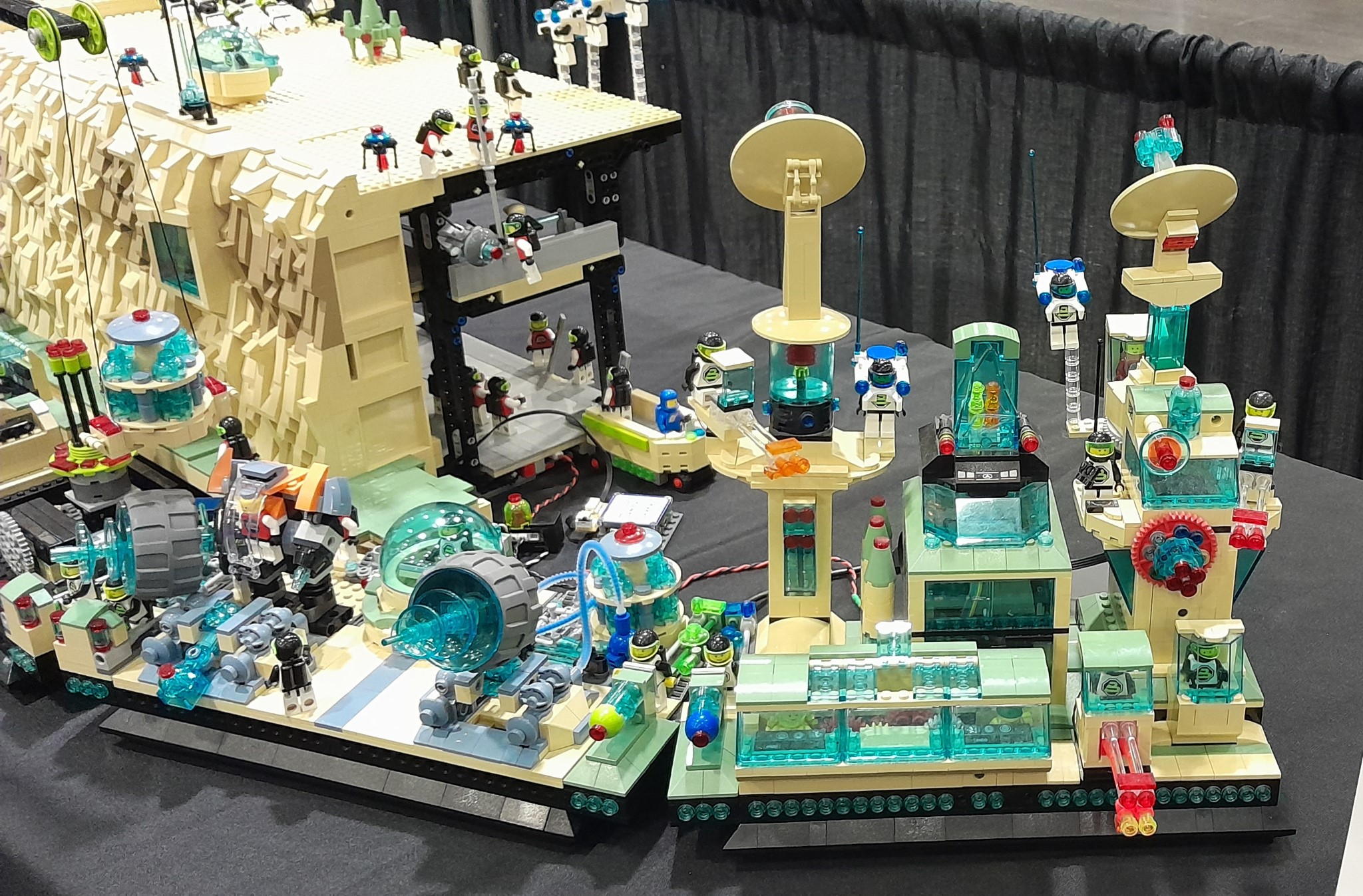
Now it is time to build out the platforms behind the cliffs.  On the other side the curved cliff platforms each had a angle on one side.  This was mostly done because one of the angles was 45 degrees.  Putting both angles on one platform, would have made that platform very small and not very usable.

In the above picture you can see that the left platform is a standard rectangle while the one on the right has angles on both sides. Because the angles are around  30 degrees, the platform does not get to be too small.

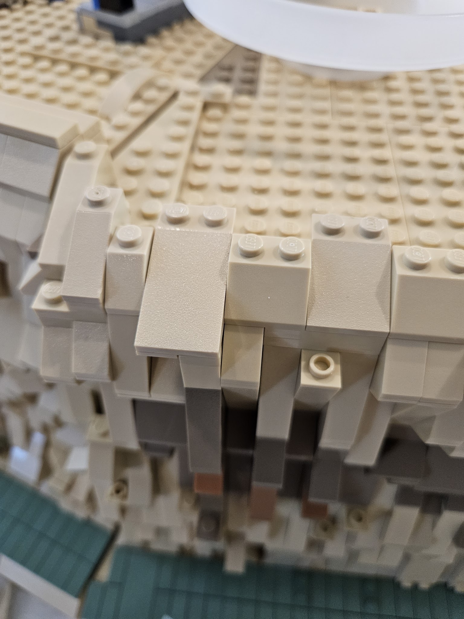
A slightly different view.  You can see the light bluish gray wedge plates that I used for the angle.  In the cliff I used either tan or dark tan wedge plates to blend in with the cliff motif.  In the platforms, the flooring will  be light bluish gray, thus the wedge plates will the same.  It helps blend in the edges wher the tiles wont be.

A better view of wedge plates.

The edges on the second floor will have to be canter levered.  So I use 4 x 4 and 4 x 6 Technic bricks to provide the support.

Then the wedge plates fit on then to form the angle.  You will notice the order of the wedge plates on the first and second floor is different.  It ends up that the 3 x 2 and 6 x 3 wedge plates are interchangeable.  Sort of like 3+2 and 2+3 give you the same answer.  On the first floor the support structure had almost infinite possibilities.  But here on the second floor with the canter lever, that is not true.  This was the only possible solution.  Plus the angle on the first and second floor had to match exactly.

On the other side the order on the first floor had changed to make the angle line continuous, so it had to change on the second floor also.

Here the first and second floors are assembled and we are doing a fit check.

A slightly different view.

Now I am working on the plateau.  Same problem as the second floor, as parts of this plateau are going to be canter levered.  The important part is getting the angles to line up.  The rest is just filler.

A view from the back.

Now I need to provide the support structure of the plateau in the cliff portion.  Before I had just used 1 x 8 bricks to do this, but that has proven to be fragile.  Here the tan plates can not be 16 x 16, they have to be something less, which will require a flexible support structure.  The 6 x 8 Technic brick with open center provides that structure.  When the plates are put on top they will tie everything together and provide a strong support structure.  

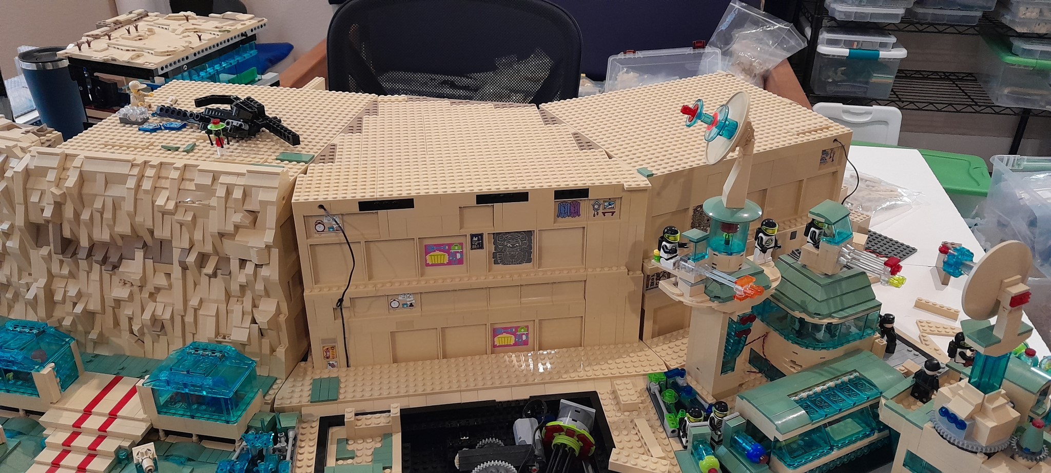
Here the plateau is done.  Also shown is the small angular piece the snaps in with Technic pins that draws the line from the main hanger platforms to the end platform.  Careful inspection of the right side will show that this extension piece sticks out one stud.  Unfortunately there is no combination of wedge plates that will match this.  The only choice is to extend the main hanger platforms one stud, but that brings with it multiple complications.  So for now there is a small mismatch.

Here is the front view, ready for rock work.  The angles came quite nice.  The left side coudl be extended some and later on I will look into this.  It would help with concealing the angular break in the rock work.