Friday, March 9, 2018

Light Cotroller PCB

Finished the prototype of the light controller last night.  Here is the PCB model.

The functionality that finally got implemented is as follows:
1. The six LP5569 LED engines were spread across the three connectors on the left, each one has two.  There are 3 LED connections per engine for a total of 6 LEDs and 4 power connections.  The connector is a standard 10 pin header and any PC 10 pin ribbon cable can be used to connect the LEDs.
2.  The connector on the bottom has the two PIC PWM engines and the two ON/OFF LEDs plus two power connections.  This connector is a the same connector used to power the Brick BuddyTM . I will have more on this later this weekend.
3.  The input control was changed to three ON/OFF type contacts and one analog input.  This way you could set the brightness or the blinking rate or who knows what I will dream up.  Again uses the same 6 pin connector as #2 above, with these four inputs and power/ground.
4.  Included a RN4020 BLE module, though I will probably not implement the firmware at this time.  This is more of a set it and forget type functionality, at least now.

The PCB fabs should be back next week, so maybe by next weekend something will be up and running.

Monday, March 5, 2018

New Light Controller (Update)


Here is the basic block diagram for the Lighting Controller.  Looks like a lot of LEDs, but to recap what is driving this.  My first battle fort had three blasters, two with 2 barrels and 1 with 4 barrels.  Then it had two power generator LEDs, one with 2 LEDs.  Finally there were two other flashing LEDs on the MOC.  That totals to 13 LEDs and ideally 6 independent controllers  I would have put in more lights, but the Brick Buddy only went had 4 independent controllers and only one had a PWM controller on it.  This is what is driving this design.

Decided to use a pair of TI LED controllers in addition to the two inherent PWM controllers inside the PIC.  The LP5569 allows for three LEDs per controller, which is 9 actual LEDs.  The IC will sink up to 25mA per  pin, so that up to two LEDs could be attached per pin with a load sharing resistor of 10 to 20 ohms.  Thus this design has up to 8 independent LED controllers.  In addition (and not shown) is two ON-OFF type signals that can sink >100mA each.

Connectors are always problematic in this type of design.  One goal is to make it small, but with all of the LED connections, this becomes difficult.  So for the 18 LEDs on the two LP5569s, I have decide to go with three standard 2x5 10 pin connectors.  These are the standard PC serial connectors and allow for use of off the shelf connectors and ribbon cables.  Still requires either soldering or twisting/taping wires.  But LEDs in a MOC can be anywhere and including a connector for every LED would take alot of room and be prohibitively expensive.  This way I don't burden the person who only wants a few LEDs with the cost of 18 single connectors.  The other two connectors use the standard 6 pin on the Brick Buddy which allows me to use those cables for other purposes.  One will connect the the sensors and the other will connect the two PIC PWM controllers and ON-OFF LEDs.

There are 4 digital sensor input and one analog sensor input.The digital sensors are all interrupt on change inputs, so the controller should be responsive to input.  The analog input would be used to vary the lighting effects, not sure how, but it is completely a frimware issue. I have some ideas for a companion board that will have a few buttons and a potentiometer on it along with some connectors to mate out to the standard power functions connector.  This will allow for standard input functions to be used.

As mentioned in the previous post, the BLE module will be optional.  I probably will not start work on the Android interface until after Maker Faire is over.  The goal would be to show a working interface at Bricks By The Bay in July.

The PCB layout has begun and right now it looks like it will all fit on 6x8 plate with a 4x8 plate on top.  This will allow for the LED lighting connectors to be exposed.

Thursday, March 1, 2018

New Light Controller

After building the first single platform MOC, it became obvious that four light controllers are not enough as the MOC gets bigger.  Therefore I am working on a new Brick BuddyTM , Light Buddy.  The basic functionality is 8 to 10 light controllers, with at least 8 of them under PWM control to provide some unique lighting effects.  Additionally a few that just power on when power is applied.  Finally some input lines that can be used to control the lights through interaction with the user or the MOC.  All of this is to be powered by a USB power source.  Optionally it will have a Microchip RN4020 BLE module included.  I am including this now because it might be useful.  But this might change as I am thinking this is more of a set and forget type functionality.

The Windows program will be the same as the Brick BuddyTM , to keep it simple for the user.  If the BLE module survives, then the same will be true for the Android app.

Right now the PIC processor that I am looking at in the 28 pin version (PIC18F26J53) will not have enough GPIO to have inputs, after the LED control, BLE Module and external memory for the user program.  Hope to have a finalized design this weekend.

First Look at Four Platform MOC


This is the first attempt at building a 4 platform MOC.  Not sure where this is headed right now.   Also not sure about the order that I want.  I have used the two angled connectors on the ends and the straight connector in the middle.  One detail I want to model is an energy control station.  The beginnings of this are on the straight connector.  The angle connectors can accept minimal detail because of the angle.  But I have ideas on how to handle.this.

I have been working on the two cylinder designs as spinning generators.  We will see where this goes.  I have modeled what the vertical one might look like here.


Monday, February 26, 2018

Platform Connectors


There needed to be a method for connecting platforms together to form one large model.  So to start here is the obvious straight connection.

Minimal Straight Connection

This shows the minimal straight connection.  It is studs wide and 18 studs deep.  This is built the same as the frame with a Technic 1x4 at the front and back and Technic 1x16 on the sides.  This is the minimum size that should be built or the two adjoining platforms will collide.  Using a 1x2 Technic brick on the front and back does not provide enough space.  The spacing can get bigger, but a 1x8 brick for the front and back is probably maximum. In order to maintain compatibility with the base platform, I added the three translucent light blue studs to the front.

In this case I put tan slopes on the connector and a sand green tile top. What detailing you put will depend on the space available and what you are trying to achieve.  I have some ideas for mine and that will be the subject of a later post.


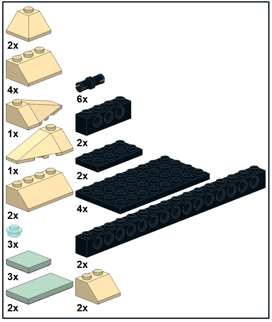
Minimal Straight Connection Parts List

Just having a straight connection did not appeal to me.  After some research and stumbling onto this in a brick pile at a flea market, started looking at how to expand this idea.
Angular connection from a Brick Pile
This led to these to angled connectors.  They can be attached in either direction, which allows for the line of platforms to return back to a straight line if desired.  One is about 20 degrees and the other is about 40 degrees.  The platforms are detailed to show what might be possible.  I have yet to decide how to detail them.  More than likely they will be some kind of energy transfer points, logistic or storage areas and the like.

First is the 40 degree angular connector showing it in both directions.

40 Degree Angular Connector in turning in configuration

40 Degree angular Connector in turning out configuration

40 Degree Angular Connector Parts List

This is the 20 degree angular connector shown in two color schemes.  Please note that the quarter round tiles did not show up in the parts list.  These are not official LDraw parts yet and could not figure out how to get LPub to include them.

20 Degree Angular Connector

20 Degree Angular Connector
20 Degree Angular Connector Parts List
NOTE:  Special thanks to LDraw and MLCad, LDView, POV-Ray and LPub3D for providing the pictures and parts list.


Sunday, February 25, 2018

Building a Base Platform


Inspired by the  MILS standard (Modular Integrated Landscaping System, http://www.abellon.net/MILS/, I built a platform that could be used to build large stations that would showcase the Brick BuddyTM  and its ability to control up to four motors and 4 sets of lights (LEDs). In order to minimize the number of different parts needed, 1x16 Technic bricks are used as the base.  This creates a frame of 32x18.  1x14 Technic bricks could have been used for the sides to get a 16x32 frame, but six 6x16 plates cover it nicely and the two extra studs width has come in handy.  Here is what it looks like as a basic frame along with the parts list.

Basic Frame  18x32

Parts List for 18x32 Frame
There is no bracing in the middle shown. This will be needed to support whatever goes on the base.  The bracing is dependent on what you are building and what access will be needed.  Typically they will be 1x16 Technic bricks or 1x16 regular bricks, but could be some combination of 2x8 regular bricks and supports to the ground.

The Translucent Light Blue studs are there for the lighting in the base.  There will be several bright LEDs inside that will light this up.  Unfortunately the technic bricks are used for pins in some models, so not all holes can be filled with these.  

The color is black, since this what I want for the base.  The plates on the top can be any color and will probably be a combination of black and tan right now.  As I said earlier my intention is to use black as the base and limited accent, with tan being the primary building color.  Color is a creative decision.

Next entry will explain the three different connectors used to interconnect the bases.

Friday, February 23, 2018

Beginning Building


This the first step to the next machines.  I have decided that the black is good for the base and limited accent, but not good for buildings as the shadows disappear.  So for now I am going with black as the base, tan as the primary building color and sand green, sand blue as the primary accent colors and black for limited use.  All of the glass will be transparent light blue.  My intention is to rebuild the model on the right to fit this new scheme.

The other item done is to standardize on a 32 x 18 platform.  This is built from six technic bricks 1x16 with holes (P/N 3703).  I then built two angled connectors for the platforms.  With these two angled connectors and the obvious straight connector, very large systems can be constructed.  More on this in the next entry.