Well the boot loader worked, at least it would come up and the PC would recognize that it was in bootload mode. I could then load a file and program it. So it all looked good. But resetting the device only brought back the bootloader. Since the bootloader was compiled hex code from a previous project, getting into it to see what was happening was going to be problematic. Besides I would have to get the professional version of the XC8 compiler to make it fit in the required space. Not something I wanted to do at this point, even for a month.
Looked at the source code to see if I could get any hints as to what was happening and compared the schematic against the one from the project the bootloader came from. And that is when the light bulb went on or the load of bricks hit me (the later being more apropos considering what this is intended for).
To force the PIC into the bootloader mode you need to hold down the push button connected to RB2. Reading a low then causes the bootloader firmware to enter bootloader mode, otherwise it will just launch the program at 0x1000. Well like any pushbutton implementation there is a pullup resistor to force the input high when the button is not pressed. And....................it was not installed. Put the resistor in and everything works the way you would expect.
Now I am off to building all of the required infrastructure (I2C, EEPROM, Timers, LP5569 driver, etc) to make the device functional.

At MyMakerTools we provide what powers your Maker projects and the Maker tools to be creative. This includes USB Power supplies to power your creations, the Maker Surprise line of Bricks & controllers, HO train goodies to make the layout stand out and soft wear to make your life just a little more comfortable.
Sunday, March 18, 2018
Saturday, March 17, 2018
Light Buddy Firmware (con't)
Back after looking for bad solder connections and the
like. I made a few last minute changes when laying out the PCB, to make
the routing more straight forward. One of these was swapping the
labels for RB5 and RB6. Well RB6 is part of the In Circuit Serial
Programmer. The fix required cutting a trace and jumping one via to a
trace. If you look real close at the PCB, just to the left of the PIC,
you might be able to see it. Need to use one strand of a 28AWG stranded
wire to do the jump. The via holes are only 10mils. Here is a better
look.

Now it connects and the bootloader loads. Maybe now we can get somewhere.

Now it connects and the bootloader loads. Maybe now we can get somewhere.
Light Buddy Firmware

Light Controller PCB Assembly
Received the PCB and started building it up. Here is the blank PCB.

My usual bring up of a new design is to install the power section and the USB connector, then test the power for shorts and opens. Once I see all of the power rails up and running I will move on to components. This is to prevent any component waste..
Here I have installed the PIC18F25K50 and its supporting parts.
 Just to the left of the processor is a pattern for a TAG-Connect programmer connection. In these tight spaces, I find this is the best. Since I usually use the HID Bootloader methodology, I use this connection once to load the bootloader and then use the USB interface for all loading and debugging (traditional printf statements).
Now it needs to be mounted so I can use it for programming. This device was designed to sit on a 6x8 plate. So I drill out the four corners with a #43 drill bit (2-56 body clearance). I use the partial holes on the back side underneath the studs as guides.


So once the 4 screws are in place, I place a another 6x8 plate on the bottom as shown here. This forces the screws to be seated all the way and makes it a lot easier to mount the spacers and PCB.


My usual bring up of a new design is to install the power section and the USB connector, then test the power for shorts and opens. Once I see all of the power rails up and running I will move on to components. This is to prevent any component waste..
Here I have installed the PIC18F25K50 and its supporting parts.

Now it needs to be mounted so I can use it for programming. This device was designed to sit on a 6x8 plate. So I drill out the four corners with a #43 drill bit (2-56 body clearance). I use the partial holes on the back side underneath the studs as guides.

This puts the holes in the center of the studs as this picture shows.

Next step is to assemble the PCB to the plate. I use 1/8" ceramic spacers for minimal clearance and 1/2" long 2-56 flat head screws. This can be problematic trying to keep the screws in place while trying to assemble the spacers, PCB and then the nuts, as this picture shows. Two of the screws have popped out of their holes.

So once the 4 screws are in place, I place a another 6x8 plate on the bottom as shown here. This forces the screws to be seated all the way and makes it a lot easier to mount the spacers and PCB.

This picture shows the mounting plate with screws and spacers ready for the PCB to be attached. The other 6x8 plate is holding the screws in place.

And finally the PCB is attached.
Now it is on to programming.
Thursday, March 15, 2018
Vertical Generator
I started building the vertical generator as a standalone model so that I can test the functionality and figure out how to light it. The base needs to be tall enough that a minifig can standup and look like they are controlling what is happening, realizing the spinning axle will be in the center. Also needs to be a roof light so that you can see everything in the control section. There will be two minfigs in there. Here is a view of the three main subsections built.


Again lighting this section is going to be challenging. This needs the random PWM lighting effect I used in the original MOC I did last year. It would be nice to also to have an LED on the top with a ramp effect which would simulate a rotating beacon. These will be task for a a later time.
The other item on the top section is should the entire enclosure be trans light blue or should the back piece be tan. The entire glass effect is nice, but the tan piece allows for hiding wires. The problem here is that you cannot center the tan piece in the back..So for now I will leave it as all glass and just figure a way to minimize the wires exposure.
I worried that the generator would wobble just enough to strike the enclosure. Testing to date has shown this not the case if everything is properly seated.
Finally here is a short video of it running.
Tuesday, March 13, 2018
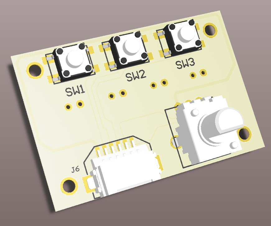
Lighting Controller Inputs/Outputs
To make it easier to control the inputs to the Lighting controller, I am making a small board with three small push buttons and small potentiometer. As in the Brick BuddyTM , there will be a script function to wait on one of these three inputs and then do something specific. The potentiometer will be used to vary lighting levels, PWM rates and burst length and randomize effects. Obviously it can do them all at the same time, but each model will be different and thus will want different effects. Here is the front side with the input controls.

To save costs, this board will be dual function. One side will do the input function, as shown above. The other side will be the output connector for the two PIC PWM controllers and the two ON/OFF LED controllers, see below. The assembly will be one or the other and not both, at least not right now.

The above are 3D models of what these look like. My only issue with the design is the connection of the outputs. Right now these are standard 0.1" spacing connectors. You can either solder directly to the PCB or put in 2 pin connectors and connect to them. Could put in the JST type connectors used by the LiPO batteries that are popular on the Maker Sites. but building mating cable connectors is difficult. In the end, it seems easiest to just wrap wires around post.
Sunday, March 11, 2018
Horizontal Generator Model
In the post on the First Look at Four Platform MOC I showed the vertical spinning generator model. The post also showed a horizontal spinning generator. I acquired four of these trans light blue 10x5 x6 half cones from one of the new Ninjago sets. I thought they looked intereesting and started playing with how to mount them. Mounting them back to back was interesting and will discuss this in a later post. I continued to play with these parts and some 10x10 octagon plates and then finally finished the model of this. Here is the model in it's current state.

I managed to hide the small gearbox in the middle. That way the drive will be underneath. Unfortunately it does not look like the longest axle will span the width, so not sure how that is going to work yet. Also still playing with the colors, may have to get my two consultants involved with that. Finally have some ideas for hoses installed to look like power cables coming out for powering the base.

I managed to hide the small gearbox in the middle. That way the drive will be underneath. Unfortunately it does not look like the longest axle will span the width, so not sure how that is going to work yet. Also still playing with the colors, may have to get my two consultants involved with that. Finally have some ideas for hoses installed to look like power cables coming out for powering the base.
Subscribe to:
Posts (Atom)