Plans change and we have to adapt. We were not accepted to the Bay Area Maker Faire this year. Since this May deadline is no longer present, I am shifting to presenting improved Lego products for Bricks by the Bay and then maybe a product for the European Train Show in July, my other passion.
While we are disappointed, there is still plenty to do for the other events coming up this year.

At MyMakerTools we provide what powers your Maker projects and the Maker tools to be creative. This includes USB Power supplies to power your creations, the Maker Surprise line of Bricks & controllers, HO train goodies to make the layout stand out and soft wear to make your life just a little more comfortable.
Monday, March 19, 2018
Vertical Generator Implementation

Sunday, March 18, 2018
Light Buddy Firmware (part 4)
Achieved all of the basic functionality, internal EEPROM, timers, USB, and the support structure. Tested all the features and they look good. What I like to do on each one of these is test the timer routines to make sure all the arithmetic was correct. You would think after about 30 of these PIC implementation, I would have this down, but I continue to surprise myself with stupid mistakes.
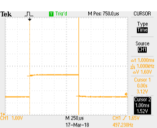
Here are three scope shots that show the pulse width for the 1ms, 10ms and 25ms timer settings. I use the timers in both a blocking function and as an interrupt driven timer. The PIC18F25K50 has two 16 bit timers that I use for this. The two 8 bit timers will be used for the PWM engines.
Here are the scope pictures.
The timing was not too bad. If the scope's calculation on frequency is correct then the actual timing was
1ms => 1.005555ms or 0.5555% error
10ms => 10.01645ms or 0,1645% error
25ms => 25.05286ms or 0,21145% error
This is good enough for timing the light s on a MOC.
Next is to install the LP5569 LED controllers and get the I2C bus working. Never used these before so it should be interesting. Plus these are very small parts, so installing is going to be fun.
Here are three scope shots that show the pulse width for the 1ms, 10ms and 25ms timer settings. I use the timers in both a blocking function and as an interrupt driven timer. The PIC18F25K50 has two 16 bit timers that I use for this. The two 8 bit timers will be used for the PWM engines.
Here are the scope pictures.
 |
| 1 ms |
 |
| 10 ms |
 |
| 25 ms |
1ms => 1.005555ms or 0.5555% error
10ms => 10.01645ms or 0,1645% error
25ms => 25.05286ms or 0,21145% error
This is good enough for timing the light s on a MOC.
Next is to install the LP5569 LED controllers and get the I2C bus working. Never used these before so it should be interesting. Plus these are very small parts, so installing is going to be fun.
Light Buddy Firmware (part 3)
Well the boot loader worked, at least it would come up and the PC would recognize that it was in bootload mode. I could then load a file and program it. So it all looked good. But resetting the device only brought back the bootloader. Since the bootloader was compiled hex code from a previous project, getting into it to see what was happening was going to be problematic. Besides I would have to get the professional version of the XC8 compiler to make it fit in the required space. Not something I wanted to do at this point, even for a month.
Looked at the source code to see if I could get any hints as to what was happening and compared the schematic against the one from the project the bootloader came from. And that is when the light bulb went on or the load of bricks hit me (the later being more apropos considering what this is intended for).
To force the PIC into the bootloader mode you need to hold down the push button connected to RB2. Reading a low then causes the bootloader firmware to enter bootloader mode, otherwise it will just launch the program at 0x1000. Well like any pushbutton implementation there is a pullup resistor to force the input high when the button is not pressed. And....................it was not installed. Put the resistor in and everything works the way you would expect.
Now I am off to building all of the required infrastructure (I2C, EEPROM, Timers, LP5569 driver, etc) to make the device functional.
Saturday, March 17, 2018
Light Buddy Firmware (con't)
Back after looking for bad solder connections and the
like. I made a few last minute changes when laying out the PCB, to make
the routing more straight forward. One of these was swapping the
labels for RB5 and RB6. Well RB6 is part of the In Circuit Serial
Programmer. The fix required cutting a trace and jumping one via to a
trace. If you look real close at the PCB, just to the left of the PIC,
you might be able to see it. Need to use one strand of a 28AWG stranded
wire to do the jump. The via holes are only 10mils. Here is a better
look.

Now it connects and the bootloader loads. Maybe now we can get somewhere.

Now it connects and the bootloader loads. Maybe now we can get somewhere.
Light Buddy Firmware

Light Controller PCB Assembly
Received the PCB and started building it up. Here is the blank PCB.

My usual bring up of a new design is to install the power section and the USB connector, then test the power for shorts and opens. Once I see all of the power rails up and running I will move on to components. This is to prevent any component waste..
Here I have installed the PIC18F25K50 and its supporting parts.
 Just to the left of the processor is a pattern for a TAG-Connect programmer connection. In these tight spaces, I find this is the best. Since I usually use the HID Bootloader methodology, I use this connection once to load the bootloader and then use the USB interface for all loading and debugging (traditional printf statements).
Now it needs to be mounted so I can use it for programming. This device was designed to sit on a 6x8 plate. So I drill out the four corners with a #43 drill bit (2-56 body clearance). I use the partial holes on the back side underneath the studs as guides.


So once the 4 screws are in place, I place a another 6x8 plate on the bottom as shown here. This forces the screws to be seated all the way and makes it a lot easier to mount the spacers and PCB.


My usual bring up of a new design is to install the power section and the USB connector, then test the power for shorts and opens. Once I see all of the power rails up and running I will move on to components. This is to prevent any component waste..
Here I have installed the PIC18F25K50 and its supporting parts.

Now it needs to be mounted so I can use it for programming. This device was designed to sit on a 6x8 plate. So I drill out the four corners with a #43 drill bit (2-56 body clearance). I use the partial holes on the back side underneath the studs as guides.

This puts the holes in the center of the studs as this picture shows.

Next step is to assemble the PCB to the plate. I use 1/8" ceramic spacers for minimal clearance and 1/2" long 2-56 flat head screws. This can be problematic trying to keep the screws in place while trying to assemble the spacers, PCB and then the nuts, as this picture shows. Two of the screws have popped out of their holes.

So once the 4 screws are in place, I place a another 6x8 plate on the bottom as shown here. This forces the screws to be seated all the way and makes it a lot easier to mount the spacers and PCB.

This picture shows the mounting plate with screws and spacers ready for the PCB to be attached. The other 6x8 plate is holding the screws in place.

And finally the PCB is attached.
Now it is on to programming.
Subscribe to:
Posts (Atom)