Friday, March 30, 2018

Vertical Geenrator Platform Build (Part 1)

Spent some time working on platforms.  I need to show mostly finished platforms at the next Baylug meeting.

 These two pictures show the below compartment taking shape.  It will have two Minifigs inside controlling the power feed into the containers (one of which can be seen later). I plan on using a blue LED backlight to light the compartment.. 

This shows the windscreen type cover for the compartment so that you can see down in.

 This was a fit check to see how everything was going to fit on it.

A first look at a mostly completed structure.  Probably going to change the slope color to sand green so that it stands out or at least surround the opening with sand green.  Still needs detailing and some structure in the front half still.

Thursday, March 29, 2018

Light Buddy Firmware (part 7)

Back to the LP5569.  I have been working on this on and off for several days and finding very little info on this.  Dont know if it will help the Maker community, but I will publishing the initialization routines, at a minimum, once I am done.

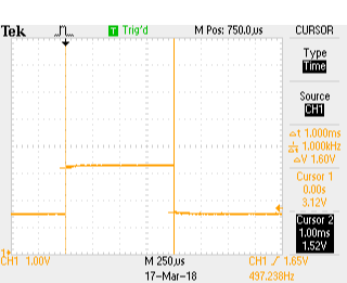
I started by writing a small set of routines to interface to the LP5569.  Then I started writing an initialization routine, followed by a status routine.  To start the testing I did some very limited writes and reads.  However everything that came back was all zeroes.  Because of the way my I2C routines are structured, I know that LP5569 is ACKing the request, otherwise the routine would hang. (Great for testing, but bad news in production.)  With out a USBEEE to decode the I2C messages, I had to resort to doing the decoding the old fashioned way, with a scope.  The scope confirmed that I indeed was getting back zeroes and that all portions of the I2C protocol was working.

I go back to the data sheet to see what I am missing.  What I was trying to do was map the LEDs to the one of the 3 Control Engines in the LP5569.  While the data sheet is not bad, it does suffer from assumption.  It is obvious that the writer was very familiar with the LP5569 and assumed the reader was almost as knowledgeable.  I had missed in the register definition section that the Engine Mapping registers were READ ONLY from I2C.  So initializing these is a waste of time.  Once I got past this the writing and read back worked much better.

The next problem was setting the PWM state for each of the nine LEDs.  Again writing did not seem to have an effect.  It always return all zeroes.  My first thought is that this was a read only register too.  But it is clearly marked R/W.  So I did a search on the data sheet for all mentions of PWM. In section 8.3..1.2.1 it says
  
"This register cannot be written when the program execution engine is active,which could result in undesirable behavior. Care should be taken to update these registers only when the program execution engine is idle."

Looked at all of the engine control registers and read them back.   All were in the default state, which is off.  The register definitions never mention idle as an Engine state, so this was causing some consternation on my part.

Continuing the search, I found in the section on LED fault detection a sequence listed.  In this sequence, you need to first enable the LP5569 through the CONTROL register (called the CONFIG register in the register summary table) and then set the PWM setting to 100%.  So I switched the order and now I can control the PWM percentage.  A few other setup registers were programed and checked, with success.  Now it is off to seeing if I can actually control the LEDs.

Wednesday, March 28, 2018

Light Buddy Firmware (Part 6)


Got some what side tracked by my day job. After the little problem with the I2C address and the fact that my UBEEE died on me, I decided to work on the PIC controlled LEDs and the sensor inputs. Here are several pictures of the unit with the sensor input attached and the LED output attached.  You will notice in the second picture that the sensor board attaches to the top of the Light BuddyTM , a nice byproduct.


The LEDs were straight forward.  They were up and running quickly using the code from the Brick Buddy.  I am not happy with the performance of the two PWM LEDs,  These are randomly generated pulse widths, which in turn give a random brightness to the LED.  While one works as expected, the second one seems to have less range of brightness.  The two channels are setup identically and programmed in the same loop.  So this is somewhat of mystery right now.  But there are bigger problems to tackle right now, since I am convinced this is not a hardware problem.

The sensors were also straight forward.  The three switches are Interrupt On Change (IOC) capable and a simple interrupt routine handled all there state.  The POT tool a little longer, acutally had to get the scope out to determine what was what.  But after making sure that all of the bits in the path were set correctly, it started delivering data.

This part is now finished and it is back to the LP5569.

Tuesday, March 27, 2018

Light Buddy Firmware (part 5)

After installing the LP5569 on one PCB the other day I have been struggling for two days to talk them.  Being 4x4mm 28 pin parts, I decided to use the reflow toaster oven to put these parts down.  While I could not find any shorts, there was no acknowledgement.

This forced me to get out my USBEE device to look at the I2C bus to make sure it was doing what it was supposed to. It confirmed that no ACK was coming back, but that the data coming out of the PIC was OK.

What I did notice though was that while I was only reading this address, the display was showing either a read or a write depending on which chip I was trying to address.  That is not right.  I went back to the data sheet to look at addresses.  Most of my experience in I2C has been where the address is in 8-bit format and the Bit 0 is not used, so you just put the address in as listed.  As you can see from this figure, that is not the case with the LP5569.  The actual byte value used needs to be shifted left one bit. 

The lesson here is to always READ THE DATA SHEET first.

Monday, March 19, 2018

Plans Change

Plans change and we have to adapt.  We were not accepted to the Bay Area Maker Faire this year.  Since this May deadline is no longer present, I am shifting to presenting improved Lego products for Bricks by the Bay and then maybe a product for the European Train Show in July, my other passion.

While we are disappointed, there is still plenty to do for the other events coming up this year.

Vertical Generator Implementation

Here is a picture of just how the vertical generator might be used.  As one of my advisers is quick to remind me, detail is what makes it real.  So I have added a lot of hoses, need some more minifigs and other details on the platform now to make it look more real.


Sunday, March 18, 2018

Light Buddy Firmware (part 4)

Achieved all of the basic functionality, internal EEPROM, timers, USB, and the support structure.  Tested all the features and they look good.  What I like to do on each one of these is test the timer routines to make sure all the arithmetic was correct.  You would think after about 30 of these PIC implementation, I would have this down, but I continue to surprise myself with stupid mistakes.

Here are three scope shots that show the pulse width for the 1ms, 10ms and 25ms timer settings.  I use the timers in both a blocking function and as an interrupt driven timer.  The PIC18F25K50 has two 16 bit timers that I use for this.  The two 8 bit timers will be used for the PWM engines.

Here are the scope pictures.
1 ms
10 ms
25 ms
The timing was not too bad.  If the scope's calculation on frequency is correct then the actual timing was

1ms    => 1.005555ms  or 0.5555% error
10ms  => 10.01645ms  or 0,1645% error
25ms => 25.05286ms  or 0,21145% error

This is good enough for timing the light s on a MOC.

Next is to install the LP5569 LED controllers and get the I2C bus working.  Never used these before so it should be interesting.  Plus these are very small parts, so installing is going to be fun.