Thursday, March 23, 2023

Cliff Wall Build Update 1

This is a simple update to show how the cliff walls are progressing.  I don't sit down and do one wall.  I find that I get into a pattern.  By working on different walls at different times, the pattern seems to stay more random.  The wall is 6 studs deep from the edge of the sand green walkway to the top of the cliff.  There are 3 studs at the base up to the first level.  Then one stud of depth is added.  This goes to the base of the top where another one stud depth is.  Finally at the top is the final single stud of depth.  Thus the cliff is fairly steep. 

Here is the start of one of the cliff walls.  This wall start is non-traditional as it has non rectangular slopes in it.  I tried to do something a little different.

Here this wall continues.  There is also a non-traditional portion of the left side.  Then I added a small platform for details to be added.  In this case it is minifig for now.

Here this one is done up to the final level going to the top.  This was finished with more traditional cliff techniques.

Here are two sections that are now done.  This one  is done in traditional techniques.

And this one has some non-traditional techniques.


Wednesday, March 22, 2023

Cliff Wall Interior Update 2

In the last post on the interior I showed mostly rendering of what was happening.  Now that I have worked out the door, I moved on to working on the interior detail at the first floor level.

In this picture you can see the large screen in the center.  The black portion will have a sticker with a screen something like this

This shows the back wall finished.  I included more brackets for more screens.  I looked at including clips for tools on either side of the large screen, but decided it would weaken the wall too much.  Unfortunately changing this later will be difficult.  The other side is the cliff with the multitude of slope parts.

I put in the light bluish gray flooring, two control panels and a few minifigs.Still need to install the overhead lighting and run the wires.  Somehow the wires will run down the right side behind the lime 1x1 round bricks on the right side.  There is a hole in the floor there which allow the wires to down and into the front right support where a connector will be installed.

The final part was to install the roof/second story floor.  If you look at a few pictures back, you see that there are two holes at the top of the wall that 6 studs apart.  This is for 1x8 beams that will help support the roof/floor.

Here is the structure.  The two 1x8 bricks are supported by two 2x14 plates.  The 2x4 bricks help hold the two plates together.  Two 2x12 bricks perpendicular to the 2x8s attach the floor to the side walls.

Then two 6x10 plates on the outside and two 6x6 plates in the center.  


 Not sure what goes on the second floor yet.  This second floor matches up with the gantry level on the hangers.  It could be office space with desks.  I need to add bunk areas but this is not the place to do it.  Or does a kitchen area make sense.  These need to be somewhere else.  For now they will be blank.


Tuesday, March 21, 2023

Solar Shed Update 2


 This is a really quick update.  The weather has been very cloudy the past few days.  So I disconnected the solar panel from the circuit.  The battery was at 14.40 VDC.  Three days later when I checked the battery, it was at 13.45VDC.  So it is obviously going to last one night and may last many days with little sun.

I have made the changes I discussed in the last Update Post.  They are installed, but there are issues.  This means I really need to take the laptop out to the shed and work on it there.  Most importantly the LED lighting turns on now. But it won't turn off.  The OLED does display the counts as an alternate screen, but it is updating too fast.  

Finally based on the voltge drop over 3 days, not sure what the super cap is going to add.  What it will do is stretch the battery out.  So if there is no solar power for many days and the LED lighting is used, it will stretch the battery in those circumstances.  Under normal operation, it is just providing a surge for the circuit.


Monday, March 20, 2023

MPLAB X Issues


I thought I would get a head start on the firmware for Brick Buddy 3 while waiting for the PCBs to arrive.  I would use the Curiosity HPC development board I had originally used in the Solar Shed project.  The HPC is on the right.

This is the only development board I have that would hold a 28 pin PIC.  I decided to just go with a PIC18F46Q71, which is the 40 pin version.  The attractive part is the two Mikroe Click sockets on this board.  One could be the RN4871 Bluetooth module and the other would some generic I2C Click board (I2C EEPROM memory) so that I can work out the I2C driver.  This was also driven by the need to check out the new common libraries I discussed earlier in this post. The Q71 family has the improved full featured standalone I2C module instead of the standard MSSP that has been in PIC18F for a very long time.  The PIC18F Q71 offered great PWM capability, 28 pin SSOP, good amount of memory ( FLASH and RAM) and some other goodies that escape me now.  Oh and I could buy it.  

And the fun begins.  There are now two versions of this Curiosity HPC.  All of the Curiosity boards have built in PICkits.  Well version 1 ( what I have) is based on PICKit3 and the version 2 on PICKit4.  And wouldn't you know it, version 1 of the HPC will not support the PIC18FxxQyy devices.  No biggee, there is a 6 pin ICSP header. I removed R13, R14, R15 which were the resistors on PGC, PGD and MCLR.  These three resistors connect back to the built in debugger.  Removing them isolates the built in debugger hardware.  I soldered on a 6 pin header to the ICSP pads, connect my PICKit4 and I should be good.

Well that was awful naive of me.  First off only the latest versions of MPLAB X will program these chips.  The earlier versions were happy to compile the code, but connect to the PICKit4, not happening.  So I downloaded the latest version MPLAB X  6.05.  It connects, blank tests, reads the memory, but when you program/debug it just hangs at the programming the configuration memory, which is the first memory area it tries to program.

This mess started last week.  I tested another 40 pin dip I had (PIC18F46K40), no issues.  So the connection is good.  So I must have damaged the PIC18F46Q71.  What else could it be.  

I was not smart enough to order two PIC18F46Q71 parts when I ordered the first one.  So another Digi-Key order and wait for arrival.  Side note: USPS delivered in 3 days, 1st class.

I then started again.  And the same result.  Posted in the Microchip Forums, not much help.  After trying all kinds of stuff, I finally went to another computer.  Maybe the computer is corrupted.  But instead of version 6.05, I installed the supposedly buggy 6.00.  And it works.  Went back to the original computer, removed 6.05, installed 6.00 and it works.  For grins, I re-installed 6.05 and it still doesn't work.  So not sure what the definition of "buggy" is anymore.

At this point I claimed victory and will just stick with 6.00 for this one project.  Filed a case and updated the forum with my results. Maybe it will save someone else the hassle. If you have acces to the Microchip forum and want more details, search for "SOLVED : PIC18F46Q71 will not program"

More than I thought to just get a simple development board up and running, but that seems to be always the case.😊


Friday, March 17, 2023

It was a Cool Idea


A few weeks ago I mused on whether I had a crazy idea or something cool (Oh so 1960s).

Well I think it is very cool, especially in its first incarnation.  The picture above was the 3D rendering of the assembly.  Here is an assembled PCB

This is the size of 1x2 Brick plate. If you solder from the back, as I will in implementation, then a 1x1 plate/tile will fit in the center.  If you solder strictly on the top, then a 1x2 plate/tile will fit.  The four solder points on the right are a little tight and some care will have to be taken when attaching wires.  Using a 250W Weller Soldering gun and 0.1" diameter solder will be challenging.

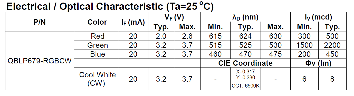
The different colors on this discrete part have different illumination characteristics as shown here.

As I suspected, some experimentation was needed to arrive at the correct resistor values.  I have set a current limit of 15mA per resistor for all of my designs.  Most of the the Light Controllers have a minimum drive current of 25mA.  So the 15mA limit sets a nice margin.  As the chart above shows, the GREEN LED is the brightest of the RGB.  It appears to be equivalent with the white.  The RED has a lower Vf, which required a larger resistor to keep the drive current under 15mA.

I needed something to test in.  I have been playing with this Design.

I started modifying this to accommodate the LED PCB.  First it needed to be in the center of the 8x8 plate.  Then I needed a way to suspend the 2x2 transparent light blue round bricks over the center, so that the light will go straight up the column and out the spire (Antenna 4H) on top.  Finally there was going to be some stack up issues when using plates and bricks and I need a way to extend the round bricks.

Here is the first step.  A 4x4 plate with a 1x1 round plate in the center.  The round plate is needed, since it fits inside the 4 studs at the center of the 4x4 plate. I glued a 1x2 tile on to the back of the PCB.  Since there are no tubes on the back of that tile, it can slide on the 1x1 round plate.  After centering the PCB I placed 1x2 bricks on the left, right side and the top left corener.  I used 1x1 round plates in stacks of three to finish the top section.  This allows the wires to pass through the gaps.  Then at the bottom (in the picture above orientation) I used 1x1 round bricks at the corners and the same stacks of 1x1 round plates in the two center positions.  This was needed to accommodate the wires that I soldered on the top, with the wires coming straight off the PCB.  If I had soldered then from the bottom, then a 1x4 brick would have worked. 

This picture shows the 4x4 assembly attached to the 8x8 plate that is on the bottom and the surround support wall, with a gap for the wires.  Now I need to support the transparent round bricks.  Modifying a brick was a possibility, but then I remembered technic plates.  They don't come in Tan, but I am not sure that matters here.

This shows the technic plate in place.  Next was a mismatch in the round brick height and the large  top (8x8 dish) that goes on top.  The round bricks actually hold this top in place, it doesn't seem to want to grab the studs on the macaroni pieces.  In the stack up that was needed to capture the LED PCB and the technic plate caused the transparent round bricks to be on plate short.  So I placed four light blue transparent 1x1 round plates on the technic plate as the picture above shows.  At first I thought I would have to drill out the technic plate hole to let more light through.  Then these four 1x1 plates sort of restrict it even more.  But as the videos below show, there is plenty of light.

So that brings back to this.

You can see the Light Buddy 2 controller on the right.I am not sure this is the final iteration of this design.  I would prefer to have the controller embedded in the unit.  Four of the six LED Channels are used, so there is no need to have it control other devices.  With some more thought, I am sure I can come up with other uses for those two LED channels.

So here are the videos. The first is in minimal background light and the second is almost full background light.  Unfortunately the camera does not have a large amount of dynamic range in light.  Thus the LED lights tend to over power the camera.  It looks much better live, but these videos give a good indication of what it can do.

Now that I see what this can do, I already have come up with RGB specific effects.  More on that later.

Minimal background light. 


 Full background light.


Thursday, March 16, 2023

Solar Shed Update


A quick update on the Solar Shed progress.  The snow has melted and there is some sun.  I have not been formerly taking down readings, but in general the battery has charged to slight over 14VDC on it at the day and about 13.8VDC in the morning.  Which is comparable to what I saw on the bench.

Moving to the real world is always going to bring on new issues.  What problems did I have, well 😛

  • For the switch that turns on the LED Lighting, for some reason the weak pullups on that input was off.  The overhead LED  lights would go on and off randomly.  I was never a fan of those weak pullups, not sure why I did not just put a 10K or 100K pullup there.  Space and cost were not a driving factor.
  • Next this switch does not wake up the PIC.  When is the PIC sleeping, at night .  When do I need the light, at night.  It is a simple fix, but I am waiting to gather more changes before fixing this.
  • I had added a relay for selecting power source for PIC and etc, from either the battery or the solar panel.  I implemented the logic to use the Solar Panel as the power source whenever it is above about 8VDC.  But forgot to change the TRIS register for the drivers to an output.  No wonder I could not drive the relay to change the source.  Now as long as there is sufficient solar panel voltage, that powers the PIC and etc.
  • All of the conversion constants moved a little, again.  1% resistors are nice, but they are still only 1% accurate.  Another change is to add an OLED screen that shows the ADC count instead of a calculated voltage.  Maybe that will help refine the conversion chart I showed earlier.
  • The 7.5F supper cap took over 2 mins to charge the first time.  I thought there was a short somewhere since the voltage would not rise.  Then I remembered that an uncharged cap is a short. 

I have been thinking of a good test for the super cap.  What I am thinking now is around 8PM disconnect the battery.  The sun will be down, so no solar power.  Then before the sun lights up the solar panel, check if the PIC is still in sleep mode.  One way is to press one of the buttons that will illuminate on the LEDs.  It is a left over debug routine, that is actually quite useful.  The other is to measure the voltage at the Suoer Cap and see if it is providing sufficient voltage.  Then this test needs to be repeated without the OLED installed.  

The process continues.


Wednesday, March 15, 2023

Building Common Libraries

Brick Controller 2

Brick Controller 3

 Light Buddy 1

Light Buddy 2


 I am up to four devices now that have some form of common LED lighting.  Two of which have motor controllers, the basic PWM interface.  As I keep developing new LED lighting effects, going back to each one of these devices and making the changes is getting too time consuming.  Not to mention that I am not getting consistent effects.  

Earlier I started on a quest to make a common library of firmware that can be updated and then automatically apply across all the device platforms.  After a few days of work and frustration 😎, I have achieved success.  Though there is still some testing to be done, but the basics work.  Here is a short description of how I got there.

The two LED controllers I am using right now are LP5569 and LP55231.  I use these because they are mostly firmware compatible with each other.  Though one is a low side driver and the other is a high side driver.  When I am not using these LED controllers, I use the built in PWM controllers in the PIC processors.  Finally when the LED is very basic, either off or on, then the control is the generic IO control of the PIC processor.  Regardless of the driving source, my hardware designs abstract the source away and present a consistent hardware interface of a low side driver.  

Both the LP5569 and LP5231 have I2C interfaces.  These were the only devices in any of these designs that had an I2C interface, thus the I2C driver was intertwined in the LP55xx code. The first step was to extract the I2C driver code and make it a standalone module.  While this was not difficult, it take some time to "unwind" all the code.  Now I can add other I2C devices, without having to include I2C driver code. 

Next was to unwrap the the LED effect (STYLE + FEATURE) from the driving source (LP55xx or PIC).  This meant creating two different modules, one for the LP55xx and one for generating the LED effect.  As has been described in previous posts, the LED effects reduces to a PWM value in either the controller or the PIC processor.  Thus the module I call PWMCtrl, generates this single PWM value for any 100ms time slice.  Then if a LP55xx is the destination, the value is passed to that module for writing into the LP55xx IC.  (Actually because of the way these ICs are set up, all nine channels are updated in a single transfer.  Thus I wait until all the LP55xx LED channels have their PWM values updated before transferring data.)  If the destination is the PIC processor, then it is a simple register update.

The final change was actually splitting the PWMCtrl module into a common section and a local section.  The local section contains all of the device initialization, the cooperative task function and any hardware dependence.  The common section is mostly the LED effects generator.  This code computes the PWM value needed. Thus I now have one place where all effects are calculated, which provides consistent looking effects.  I have not looked very carefully at this split.  There probably is a way to combine these through some MACRO definitions.  But that will be for later.....